High Quality Chainsaw Bars Husqvarna Toys Hockfire Saws

The LT42e Chronicles: A Tale of Wires, Woe, and Mild Electrocution

odonnse

Active OPE Member
Local time
7:12 AM
User ID
30375
Joined
Oct 29, 2024
Messages
7
Reaction score
6
Location
USA
Country flag
Greetings, fellow yard warriors and electric tractor whisperers.


Let me regale you with the epic saga of my Cub Cadet LT42e, a fine machine that decided it no longer wanted to participate in basic lawn maintenance and instead threw a tantrum in the form of error codes E108, E113, E115, and E116. If this thread helps just one poor soul avoid a mid-mow existential crisis, then my solder burns and sanity loss were not in vain.


Now, a little context: I’m an electrical engineer by trade and run a wiring harness business, so when this thing started speaking in CAN bus riddles, I figured I’d be the one to crack the code. What I didn’t expect was to descend into a rabbit hole so deep, I may now qualify for Cub Cadet’s unofficial electrical engineering team. (Don’t worry, they won’t return my emails either.)


Error Codes & Cub Cadet Support (Or Lack Thereof)​


Reaching out to Cub Cadet for support was about as helpful as asking my cat to read a wiring diagram. The good news? This forum came to the rescue like a pit crew at a NASCAR race. Big thanks to the legends here.


Step 1: The Disassembly Olympics​


After peeling this thing like an electric onion, I discovered the contactor wasn’t closing. Translation: the three motor controllers were basically just very expensive paperweights. Cue dramatic gasp.


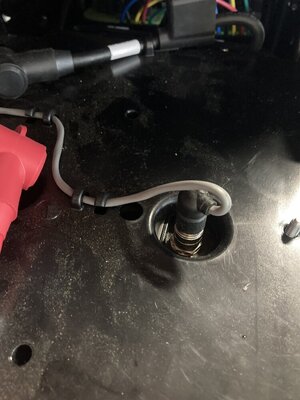
Upon further inspection, I found some impressively pinched wires a few inches down from the PDM connector on the main harness. Apparently, Cub Cadet believes in tight wire routing—as in “banjo string” tight. Just enough tension to double as a cheese slicer.


Step 2: PDM Bench Testing – Mad Scientist Mode​


I pulled the PDM and did what any sane person would do: rigged it up on the bench with a 31V power supply, 12V auxiliary, some alligator clips, and sheer stubbornness. It clicked. Lights came on. Birds sang. The Anderson connectors showed voltage. Victory!


Step 3: The Harness Odyssey​


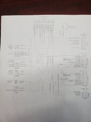
Feeling victorious and slightly caffeinated, I yanked the entire main harness to document the pinouts and fix the damage. With the help of old wiring diagrams, a zero-turn troubleshooting guide, and some good ol’ fashioned beep-boop continuity checking, I began to decode the sacred texts of the LT42e.


Step 4: VCM — The Mysterious Black Box of Doom​


Here’s where it gets fun (read: maddening). I wanted to see if the VCM was doing its job. So I Frankensteined the harness back together, skipped the non-essentials (sorry, headlights), and began probing like a dentist at a candy convention.


Pin 8? 12V for a few seconds—beautiful. Pin 4? Nada. Zip. Zilch. Suspicion turned to the VCM.


Naturally, I cracked it open like a crab at a seafood boil. Turns out, it's full of tiny little voltage regulators stepping 12V down to 5V and 3.3V—like a Russian nesting doll of disappointment. There’s a microcontroller that should drive 3.3V to a mystery component (my money’s on a transistor), which then activates the coil + and pre-charge signals. Spoiler: mine did not.


I even desoldered this “mystery meat” component, hoping to unlock the secrets of the universe. But no dice. Still no 3.3V. Yet the display works, error codes flow like wine, and other signals are acting normally. So the micro isn’t dead... just moody.


Where I’m At:​


Staring down this VCM like it's an old nemesis in a Western showdown. If anyone has a working VCM they’d be willing to donate to science (or sell for a non-kidney price), I’d be forever grateful. Also, if you have ideas why the VCM might ghost the Coil+ signal, please drop some wisdom.


Bonus: Gen 2 VCM Fault Codes​


I managed to pry some fault code info from Cub Cadet’s customer service vault before they slammed the door shut. I attached them in case anyone else is deciphering these hieroglyphics.


Thanks for coming to my TED Talk. May your circuits be sound and your blades sharp.
 

Attachments

blades

Super OPE Member
Local time
7:12 AM
User ID
7181
Joined
Aug 30, 2018
Messages
345
Reaction score
555
Location
Leroy, WI
Country flag
i worked on re-pro-graphic equipment during the era of switching over from tubes ( power supplies) and mechanical switches and cams to solid state devices and into the LSI ( large scale integrated circuits ) times. Schematics were almost useless as the the progression was so rapid that the schematics supplied by the mfg were as much as 6 generations behind what was being shipped very similar to home computers of the 80's-90's. And the there was the a bit of a language barrier between MFG and us. Getting my guys to understand that the error codes later on were a result of a failure further upstream was at best difficult. And ya the wiring harnesses were very taunt, chassis edges were left as stamped ( read razor sharp). didn't take much abrasion to cut though those tiny plastic coated wire bundles and cause intermittent shorts which of course generated an error codes. Or streched to tight causing breakage of the wire inside the plastic insulation ( particularly fun to correct).
 

odonnse

Active OPE Member
Local time
7:12 AM
User ID
30375
Joined
Oct 29, 2024
Messages
7
Reaction score
6
Location
USA
Country flag
Don't get me wrong, when I develop a harness for a vehicle, I like to keep them as short as possible. But these harnesses are so tight it some areas, it feels like they are using it to hold the thing together!
 

FergusonTO35

Here For The Long Haul!
Local time
8:12 AM
User ID
3545
Joined
Jul 9, 2017
Messages
5,547
Reaction score
13,383
Location
Boonesborough, KY
Country flag
Cutting edge technology executed by a second or third tier manufacturer like today's Cub Cadet is always an invitation to disaster!
 

odonnse

Active OPE Member
Local time
7:12 AM
User ID
30375
Joined
Oct 29, 2024
Messages
7
Reaction score
6
Location
USA
Country flag
Cutting edge technology executed by a second or third tier manufacturer like today's Cub Cadet is always an invitation to disaster!
I totally get where you're coming from! Cutting-edge tech in the hands of a second or third-tier manufacturer can feel like giving a toddler a loaded Nerf gun—sure, it might hit the mark, but it’s more likely to end up with a shot to the foot and some serious regrets. As much as I appreciate the gaskets over goop and the surprisingly neat harness looming (a small victory in a world of spaghetti wiring), there are still some “head-scratcher” moments—like random through-hole resistors dangling off wires for hardware configuration. It's like they decided to toss in some premium tech, but forgot to make sure the basics were covered.

With a brand like Cub Cadet, it’s a gamble. It’s like they took the latest and greatest features, handed them off to an engineering team that specializes in "creative solutions," and said, “Just make sure it runs long enough to get through the warranty.” So, yeah—cutting-edge tech with a unique twist. Disaster or brilliance? You be the judge!
 

FergusonTO35

Here For The Long Haul!
Local time
8:12 AM
User ID
3545
Joined
Jul 9, 2017
Messages
5,547
Reaction score
13,383
Location
Boonesborough, KY
Country flag
My Cub Cadet tiller works because it's a simple as dirt design originally created by White Farm Equipment and has a Honda engine.
 

odonnse

Active OPE Member
Local time
7:12 AM
User ID
30375
Joined
Oct 29, 2024
Messages
7
Reaction score
6
Location
USA
Country flag

Return of the VCM: The LT42e Resurrection, Part 2


(Or: How I Learned to Stop Worrying and Love the Short Circuit)


Hello again, fellow electric tractor tamers and backyard engineers.


If you remember Part 1, I was locked in a dramatic standoff with my Cub Cadet LT42e. The VCM, that mysterious black box of dashed hopes and error codes, had become my nemesis. Thanks to a generous loan, I finally got my hands on a known-good VCM to test my working theory. I installed it with hope in my heart.


Spoiler: It didn’t work. Same error codes. My wife sighed knowingly. I stared blankly at the mower. We were back at square one, just with slightly more desoldered components and existential dread.


Troubleshooting Reloaded: Finding the Real Culprit


Rather than declare defeat, I doubled down. This time, instead of poking things at random and blaming the VCM, I tried isolating each motor controller on the mower itself—not bench testing. One at a time, I disconnected two controllers, left one connected, and powered the mower.


To be clear: I used 31V because that’s literally the maximum my bench power supply could provide. I would’ve gone higher, but unless I wanted to hook up jumper cables to the sun, 31V was all I had.


As I went through each controller, I carefully watched the error codes:


  • Left blade controller? No overload.
  • Drive motor? No issue.
  • Right blade motor? Boom—current maxed instantly. Error codes stayed. Current limit pegged.

Bingo.


Decoding the Power-Up Ritual


Here’s what I believe now is the LT42e startup sequence, based on reverse-engineering, observation, and a bit of frustration-fueled enlightenment:


  1. Key inserted and pushed in: The VCM sends out a 12V pre-charge voltage. This doesn’t go through the contactor—it flows through series resistors inside the VCM and reaches out to the motor controllers and sensors.
  2. Diagnostic phase: If everything’s happy and responding over CAN, the VCM says, “Cool,” and sends 12V to the contactor coil.
  3. If something’s unhappy? The VCM throws a silent tantrum. No contactor. No voltage. No mow.

My right blade motor controller had a dead short from power to ground. That pulled the pre-charge line down to zero, effectively turning off all the controllers by starving them of power. No power, no CAN, no handshake. So the VCM did its job: it said no.


The Deepest Dive Yet: Opening the Motor Controller


With the harness in pieces, VCM cracked open, and my pride bruised, I decided to operate.


I opened the right blade motor controller like it was Thanksgiving dinner. A few capacitors came off to expose the internals. Sure enough, a power trace was glowing under load like a toaster coil. Let’s call it what it was: a hot, smoldering short.

20250508_222432.jpg


Pro tip: If you don’t have a thermal camera, you can also give the circuit 3 amps and wait for smoke signals.
Disclaimer: That’s a joke. Please don’t actually do this unless you enjoy turning your components into charcoal briskets. You’ll probably just cook something else in the process—ask me how I know.


Once I dug out the carbonized debris (which I assume used to be something important), I applied solder mask to rebuild the trace’s integrity and reinstalled the capacitors I had removed during the diagnosis. Then came the VCM reassembly—specifically reinstalling the mystery meat transistor, about 2mm x 2mm (roughly five cow hairs in width, for us metric-averse folks).

20250506_213810.jpg


To my surprise, it still worked.


Click. Glorious Click.


With everything hooked back up and parts back in their places, I pushed in the key.


Click. The contactor engaged.


I didn’t scream with joy, but only because I was too stunned. The mower worked. I even mowed the lawn. It was the most satisfying patch of grass I’ve ever trimmed.


Bonus Discovery: The CAN Translator Box


Inside the motor controller, I also found an interesting sidecar PCB encased in what looked like a copper Faraday cage, soldered directly into the main board. Naturally, I desoldered it.


It turned out to be a simple daughterboard with a few CAN-related ICs and passives—likely to translate CAN to something the main controller microcontroller understands.


My theory: This tiny board is what differentiates a left motor controller from a right one. That means, in theory, if you’re savvy with a soldering iron, you could grab any used LT42e or ZT1-42e motor controller, swap in your original CAN board, and poof—it becomes the correct one.


I’ve got a candidate controller on the way (from the ZT1, possibly for the left side), and yes, I’m going to crack my mower open again to test this theory.


Bonus Bonus: Full Wiring Diagram


Attached below is the full LT42e wiring diagram, featuring a single-VCM setup (with either the “leaf” or “!” icon button pad). Hopefully, this helps future troubleshooters skip past some of the pain.


Final Thoughts


These machines are absolutely repairable—with patience, a good iron, and respect for high-voltage systems. They just happen to be wrapped in layers of obfuscation and mediocre support.


I hope this helps someone out there who’s lost in Cub Cadet CAN-bus purgatory. I’m happy to answer questions or share part numbers, pinouts, or colorful metaphors.


Stay tuned for the motor controller transplant update. Until then—may your resistors stay cool and your diagnostics stay sharp.
 

Attachments

  • 20250508_120352.jpg
    20250508_120352.jpg
    84.4 KB · Views: 3

odonnse

Active OPE Member
Local time
7:12 AM
User ID
30375
Joined
Oct 29, 2024
Messages
7
Reaction score
6
Location
USA
Country flag
So… turns out the wiring diagram I mentioned? Yeah, it’s basically useless. Way too blurry to be helpful. My scanner decided to join the LT42e in rebellion and refused to cooperate.

I’m working on getting a proper scan uploaded soon—one that doesn’t look like it was faxed from the moon. Sit tight if you were hoping to trace wires without a magnifying glass and divine intervention. It’s coming!
 

odonnse

Active OPE Member
Local time
7:12 AM
User ID
30375
Joined
Oct 29, 2024
Messages
7
Reaction score
6
Location
USA
Country flag
Here is the scanned version of the wiring diagram. Should be more clear, it was a scan of a printed copy.
 

Attachments

blades

Super OPE Member
Local time
7:12 AM
User ID
7181
Joined
Aug 30, 2018
Messages
345
Reaction score
555
Location
Leroy, WI
Country flag
Great you found the problem, skipping around and just wild assumptions seldom get anywhere quick. With all this new fangled self destructing equipment one has to follow the operating sequence to get anywhere. That was the hardest thing to teach to new service people I ever had to do.
 

odonnse

Active OPE Member
Local time
7:12 AM
User ID
30375
Joined
Oct 29, 2024
Messages
7
Reaction score
6
Location
USA
Country flag
100%, effective troubleshooting is an art form. Usually helps to have some technical documentation from the manufacturer. This was very much a reverse engineering exercise with a bit of repair sprinkled in for good measure.
 
Top