High Quality Chainsaw Bars Husqvarna Toys

Part One: The Exhaust Port

RIDE-RED 350r

Here For The Long Haul!
Local time
11:15 AM
User ID
839
Joined
Feb 8, 2016
Messages
3,228
Reaction score
12,760
Location
Blossvale NY
From what I have seen on the scene, Rotax's exhaust valve is one of the best, simplest, and most reliable exhaust valves going. It's officially called the R.A.V.E. (Rotax Adjustable Variable Exhaust). I could see the benefit in situations like Deets and Junkman cite. Look in the snowmobile world for most of the best exhaust valves going. Only problem is size and reworking the exhaust to physically allow clearance for the exhaust valve.
 

XP_Slinger

They’re Just Saws
Local time
11:15 AM
User ID
845
Joined
Feb 9, 2016
Messages
6,089
Reaction score
27,524
Location
Central NY
Country flag
I also see power valves as useless on a saw. When do we ever cruise through a log at 1/4 throttle and blip it in the cut to cut a little faster? Saws are built to run WTFO, no variable exhaust timing necessary to achieve desired performance because at that point the power valve is out of the picture.
 

junkman

Crush it
Local time
8:15 AM
User ID
388
Joined
Jan 3, 2016
Messages
4,312
Reaction score
17,030
Location
pacific northwest
Country flag
I also see power valves as useless on a saw. When do we ever cruise through a log at 1/4 throttle and blip it in the cut to cut a little faster? Saws are built to run WTFO, no variable exhaust timing necessary to achieve desired performance because at that point the power valve is out of the picture.
I run partial throttle milling a lot,keep the rpm steady for a smooth board. Between 7 and 9k mostly on the tach limbing logs seldom go over half throttle also.
 

PogoInTheWoods

Pinnacle OPE Member
Local time
11:15 AM
User ID
1190
Joined
Apr 23, 2016
Messages
1,943
Reaction score
3,850
Location
Ohio
Country flag
First, I'm seriously impressed by all the knowledge and ideas being shared for 14 whole pages in such a civilized manner. Scary!

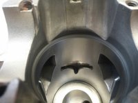
Second, I've not done any port work aside from cleaning carbon out of an exhaust port. Then I recently rebuilt a Mac PM8200 with the infamous 'Q' port. Not only is the exhaust port around 30% smaller than the intake port, it screamed to be widened with at least the parts of the roof on each side of the arch being cleaned out somewhat (if nothing else) since there is a distinct dividing ridge between each side (top and bottom) of what otherwise is a slightly rounded port exit from the inside out..., in other words, not at all flat. It sure seemed like even some minimal grinding could make a huge difference for the better by opening things up a bit. I asked a couple of the Mac gurus what they thought about it and came away with a basic understanding that the design is somehow associated with varying/dynamic compression characteristics between low and high RPM's relative to load, etc., and I should leave well enough alone and let the transfer design take care of any concerns I may have about the exhaust port design. Who was I to argue? One of the guys mentioned he thought Randy may have weighed in on the subject somewhere along the line but couldn't remember specifics.

Based on the subject and extent of this thread, (not to mention the participants), it seemed like a good place to float this out for opinions and observations..., or for anyone who has actually ported one of the 82cc Mac 'Q' port saws.
Still has me scratchin' my head.

0412171605_resized.jpg
0412171558_resized.jpg
 

XP_Slinger

They’re Just Saws
Local time
11:15 AM
User ID
845
Joined
Feb 9, 2016
Messages
6,089
Reaction score
27,524
Location
Central NY
Country flag
First, I'm seriously impressed by all the knowledge and ideas being shared for 14 whole pages in such a civilized manner. Scary!

Second, I've not done any port work aside from cleaning carbon out of an exhaust port. Then I recently rebuilt a Mac PM8200 with the infamous 'Q' port. Not only is the exhaust port around 30% smaller than the intake port, it screamed to be widened with at least the parts of the roof on each side of the arch being cleaned out somewhat (if nothing else) since there is a distinct dividing ridge between each side (top and bottom) of what otherwise is a slightly rounded port exit from the inside out..., in other words, not at all flat. It sure seemed like even some minimal grinding could make a huge difference for the better by opening things up a bit. I asked a couple of the Mac gurus what they thought about it and came away with a basic understanding that the design is somehow associated with varying/dynamic compression characteristics between low and high RPM's relative to load, etc., and I should leave well enough alone and let the transfer design take care of any concerns I may have about the exhaust port design. Who was I to argue? One of the guys mentioned he thought Randy may have weighed in on the subject somewhere along the line but couldn't remember specifics.

Based on the subject and extent of this thread, (not to mention the participants), it seemed like a good place to float this out for opinions and observations..., or for anyone who has actually ported one of the 82cc Mac 'Q' port saws.
Still has me scratchin' my head.

Those are some wild lookin ports. Never seen the like in my inexperienced tinkering. I'm scratching muh head along with ya.
 

PogoInTheWoods

Pinnacle OPE Member
Local time
11:15 AM
User ID
1190
Joined
Apr 23, 2016
Messages
1,943
Reaction score
3,850
Location
Ohio
Country flag
For those mentioning the technique of a piston modification in combination with port shape for gains, the pistons in these 'Q' port top ends have a markedly narrower skirt on the exhaust side than the intake side. Maybe they're working together with those rather cool (and huge) transfers to do the magic?
 

Larry Joe

Well-Known OPE Member
Local time
8:15 AM
User ID
1050
Joined
Mar 19, 2016
Messages
46
Reaction score
154
Location
Northern California
Thank you Deets sorry. I have never used Craytex but have the white compound with a price of green scotch brite.

Sent from my SM-G935V using Tapatalk
Cratex is great stuff, the bullet shaped points are great for finishing. It does leave a lot of dust behind . After blowing it out I always wash cylinders with lots of hot soapy water and scub all ports with little bottle type brush's.
 

Larry Joe

Well-Known OPE Member
Local time
8:15 AM
User ID
1050
Joined
Mar 19, 2016
Messages
46
Reaction score
154
Location
Northern California
I wanna build a jug with a power valve......
How about an anti reversion cone ? Maybe a flange matched to the exhaust gasket with a short necked down cone that extends Into the muffler 3/4" or so ? You could also make one of these with a "lip" that rests in the bottom of the exhaust port (shallow inletting in Port floor so it is flush) with this type of set up you could experiment with location and height of the exhaust step by hard soldering the step. Only have to use one cylinder as a test mule. Just a thought.
 

Mastermind

Chief Cat Herder
Staff member
GoldMember
Local time
10:15 AM
User ID
4
Joined
Dec 3, 2015
Messages
48,346
Reaction score
314,506
Location
Banner Springs Tennessee
Country flag
How about an anti reversion cone ? Maybe a flange matched to the exhaust gasket with a short necked down cone that extends Into the muffler 3/4" or so ? You could also make one of these with a "lip" that rests in the bottom of the exhaust port (shallow inletting in Port floor so it is flush) with this type of set up you could experiment with location and height of the exhaust step by hard soldering the step. Only have to use one cylinder as a test mule. Just a thought.

I'd need pics or drawing to fully understand what you mean......but if I'm following correctly, you might be onto something.
 

Deputyrpa

Super OPE Member
Local time
11:15 AM
User ID
3090
Joined
Apr 27, 2017
Messages
209
Reaction score
588
Location
Fort Ann, NY
Country flag
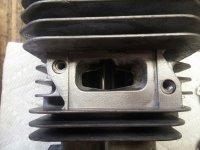
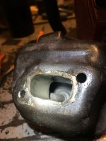
034 exhaust roughed in. This is just a mild job to get my feet wet. Used a Dremel flex shaft with a high speed cutter at low speed. The sides are symmetrical even though it looks off - camera angle. I widened it a bit and raised the roof a touch, but made the sides and kept the top squarish. I also increased the down angle on the floor, mostly. I have yet to bevel the inside edge. Comments please.
20170506_171136_zpsjkapdm36.jpg

20170506_171317_zpsr5dln7gs.jpg
 

huskihl

Muh fingers look really big
GoldMember
Local time
11:15 AM
User ID
360
Joined
Dec 31, 2015
Messages
22,558
Reaction score
143,638
Location
East Jordan, MI
Country flag
034 exhaust roughed in. This is just a mild job to get my feet wet. Used a Dremel flex shaft with a high speed cutter at low speed. The sides are symmetrical even though it looks off - camera angle. I widened it a bit and raised the roof a touch, but made the sides and kept the top squarish. I also increased the down angle on the floor, mostly. I have yet to bevel the inside edge. Comments please.
20170506_171136_zpsjkapdm36.jpg

20170506_171317_zpsr5dln7gs.jpg
Looks good to me. Bevel the edges and blow it out and slide the piston in there and check concentricity. Make sure the bottom of the port is rounded as well, as the rings travel over that too.
 

Larry Joe

Well-Known OPE Member
Local time
8:15 AM
User ID
1050
Joined
Mar 19, 2016
Messages
46
Reaction score
154
Location
Northern California
I'd need pics or drawing to fully understand what you mean......but if I'm following correctly, you might be onto something.
It's hard to describe. I could draw it no problem. Do a Google image search for anti reversion cone. You know how a stiker plate for a door lock looks, it has the tab folded back that goes into the hole and the plate is flush to the door frame. Imagine the plate is made to port match your exhaust and you punch or cut 3/4 of the way around the opening, then bend the material at the scored line leaving it attached and going into the port. Trim so the tab fits the taper of the exhaust port and and the end is just shy of the cylinder wall. Scribe a line around the tab onto the floor of the port, remove material within scribed line to depth of material used for plate. A Foredom engraver with a wide cutter would do the job. So the plate/gasket has the tab laying in the channel you have created. You could make "steps" out of mild steel and solder them to the tab, allowing you to move them back and forth or build them up looking for a "sweet spot". A short tapered pipe brazed to the muffler side of the plate would go into the muffler, the muffler being matched to the OD of the pipe. Length of pipe into muffler may have tuning possibilities also. It would take some time to make but it would allow a lot of testing on the same jug, all of it revesable. I can't believe I just typed all this. Typing sucks ! I know just enough to be dangerous about this stuff. I can have a 3D drawing done in CAD or Revit if you want it, that's what my wife like woman does.
 

Stihlbro

Pinnacle OPE Member
Local time
11:15 AM
User ID
310
Joined
Dec 29, 2015
Messages
1,098
Reaction score
4,799
Location
Virginia
Country flag
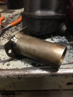
IMG_1915.JPG

Small extension.

IMG_1916.JPG

Made this for a 026. Tried to route the exhaust out and down to the left. Not much different on tune and did not add anything.

IMG_1918.JPG

Plain and simple. Too Loud!!!!!

I see the concept being similar to a header. What Larry Joe is speaking of it more of a tapered cone to induce some back stuffing like a pipe does. Not straight like my pic.
 
Top