You are using an out of date browser. It may not display this or other websites correctly.
You should upgrade or use an alternative browser.
You should upgrade or use an alternative browser.
The LT42e Chronicles: A Tale of Wires, Woe, and Mild Electrocution
- Thread starter odonnse
- Start date
jwax
OPE Member
I notice the XT1 wiring diagram is missing some components like the motor controllers, 20 Amp fuse, and the 4-pin CANBUS connector on the battery. Are there other schematics from your source? Thanks again!
odonnse
Well-Known OPE Member
The wiring diagram is just for the main harness. The motor controller power comes from the PDM. And the CAN bus connector you see in the drawing is what connects to the CAN bus harness for the motor controllers. But the main harness connects directly to your BMS with a deutsch style connector.
odonnse
Well-Known OPE Member
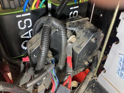
I believe that is the PDM (Power Distribution Module). Your earlier system looks a bit different than mine, but I believe that is it. That is what houses the contactor that gives the "click" when the VCM (Vehicle Control Module) says everything is good. If you have error codes, most of the time the VCM will not give the PDM the "go for launch".
So just to get is straight, your charger gives you an error code and your VCM gives you an error code? Can you share an image of those or share what they say? Also was the battery fuse good?
So just to get is straight, your charger gives you an error code and your VCM gives you an error code? Can you share an image of those or share what they say? Also was the battery fuse good?
jwax
OPE Member
Thanks! There's no code from the VCM, or the mower. The mower simply does nothing with the switch to ON.
The only error code is from the Delta-Q charger- E004
Tempted to gut the wiring harness, and use 48 volts to the blade motor, and the drive motor controller to drive the drive motor. Simple!
The only error code is from the Delta-Q charger- E004
Tempted to gut the wiring harness, and use 48 volts to the blade motor, and the drive motor controller to drive the drive motor. Simple!
odonnse
Well-Known OPE Member
I would be reluctant to do that, easy way to cause a catastrophic failure of your batteries and start a fire if you are not careful. Does your VCM turn on at all? It is odd that you are getting an error code on one thing but not the other.
jwax
OPE Member
Never have seen an error code on the simple little display on the mower. Just, "Depress Brake Pedal", "Close charger Door", etc.
Anyway, it's done- spent this holiday gutting the wiring. Down to a cutter motor, and a drive motor. Now just need to drive the two.
Interestingly, both motors are labeled, "48 VDC", but wires/controller are obviously 3-phase. Curious!
No, VCM never activates.
Anyway, it's done- spent this holiday gutting the wiring. Down to a cutter motor, and a drive motor. Now just need to drive the two.
Interestingly, both motors are labeled, "48 VDC", but wires/controller are obviously 3-phase. Curious!
No, VCM never activates.
odonnse
Well-Known OPE Member
The motors are most likely DC motors. The motor controllers will drive a square wave to alternate per phase of the motor based on the speed input provided. Obviously the blade motors will be driven at a constant speed and the drive motor will be variable. I guess your model version has some more differences than I expected. The VCM provides most of the system error codes.
jwax
OPE Member
Correct! Found they are Brushless DC motors (BLDC), requiring 3 inputs to drive it. Now to figure out the Hall-effect wiring which is necessary for the controller to control speed.
What complicates this relatively simple concept of battery and motor to make things work is that pesky CANBUS. Don't need it, don't want it.
But seems every part of the mower is dependent on its hidden signaling. Not my mower. not any more.
Waiting to see schematics from ASI controls, who built the controllers. Then I can put it all together.
Delta-Q charger already told me their charger needs CANBUS signals to output a charging voltage. I have other chargers.
Thanks for helping, and following along!
odonnse
Well-Known OPE Member
Wow, you have really dove in! I appreciate the initiative and good luck on your goal, let me know if I can help. Not sure about your system, but on the newer the motors themselves also communicate over CAN. Really the only thing that does not communicate over CAN is the PDM, brake switch, TPS (throttle position sensor), and seat safety switch.
blades
Super OPE Member
- Local time
- 5:26 PM
- User ID
- 7181
- Joined
- Aug 30, 2018
- Messages
- 390
- Reaction score
- 658
- Location
- Leroy, WI
Those hall effect circuits are noted for failing across everything they are put in. Kinda like when mosfets first appeared. If you looked at them cross-eyed they failed, or the cheap capacitors used by one particular computer mfg in 90's.
jwax
OPE Member
You have obviously been in the electronics repair business by your comments- me too.
Next I have to figure out the wiring of those Hall effect devices from the wires coming from the Deck motor. Then I could use a generic BLDC motor controller. ($50). Any ideas on how to identify those wires? There's 6- Blue, Green, and yellow (the three phases), Black and Red (5 volt power), and a White. What's could the White be for??
Next I have to figure out the wiring of those Hall effect devices from the wires coming from the Deck motor. Then I could use a generic BLDC motor controller. ($50). Any ideas on how to identify those wires? There's 6- Blue, Green, and yellow (the three phases), Black and Red (5 volt power), and a White. What's could the White be for??
el33t
Super OPE Member
- Local time
- 12:26 AM
- User ID
- 29908
- Joined
- Aug 28, 2024
- Messages
- 277
- Reaction score
- 690
- Location
- Poland
You have obviously been in the electronics repair business by your comments- me too.
Next I have to figure out the wiring of those Hall effect devices from the wires coming from the Deck motor. Then I could use a generic BLDC motor controller. ($50). Any ideas on how to identify those wires? There's 6- Blue, Green, and yellow (the three phases), Black and Red (5 volt power), and a White. What's could the White be for??
Temperature sensor?

FLIPSKY Dual Mini FSESC6.7 Pro 140A base on VESC6.6 With Aluminum Anodized Heat Sink
Flash Deals FLIPSKY Dual Mini FSESC6.7 Pro 140A base on VESC6.6 With Aluminum Anodized Heat Sink
 flipsky.net
r7000
Well-Known OPE Member
Greetings...
why does a riding mower need CANBUS ?
do you know what stuff on your model cub cadet electric rider necessitates the need for it?
taekeshionin
New OPE Member
jwax
OPE Member
"why does a riding mower need CANBUS ?" Very good question! Guessing that the government elected to, "protect the public" and requires all the safety gadgetry. Manufacturers thought CANBUS would make that easy for them. Also, brings in cash for dealers that service these computerized marvels. Banning the DIY guy from repairing it themselves.
As for what is on the CANBUS river, is the charging system, battery, motor controllers, seat switch, chute switch, and I don't know what else. Suffice to say that if there is an error, the mower is a boat anchor.
Apparently there are diagnostic cables that allow one to do some troubleshooting, but like most "troubleshooting guides", for most issues they say to return to dealer (and bring your wallet).
My gutted E150 runs great without the digital wizardry, and now going through different BLDC motor controllers to find one robust enough. ASI, Inc. (Canada) stock controllers (CANBUS enabled) do not respond to my emails, phone calls, even postal mail asking for tech data on their products.
legdelimber
Pinnacle OPE Member
Any of you guys ever look in over on Hackaday.com ?
Might be a starting point for looking around in their postings?
https://hackaday.com/tag/bldc/
This crowd is heavy on the DIY and modding and/or scratch building of many types of things, unlocking features etc..
Lots of ideas and opinions on many topics, over there.
Might be a starting point for looking around in their postings?
https://hackaday.com/tag/bldc/
This crowd is heavy on the DIY and modding and/or scratch building of many types of things, unlocking features etc..
Lots of ideas and opinions on many topics, over there.
Similar threads
- Replies
- 0
- Views
- 312
- Replies
- 3
- Views
- 2K


