High Quality Chainsaw Bars Husqvarna Toys Hockfire Saws

Let's Build a 266

jacktheripper

Papa Squat
GoldMember
Local time
11:59 PM
User ID
28875
Joined
Apr 5, 2024
Messages
497
Reaction score
1,841
Location
Wyoming
Country flag
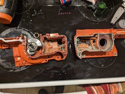
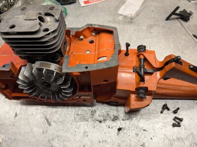
Step 3: Install clutch side case half, mate cases

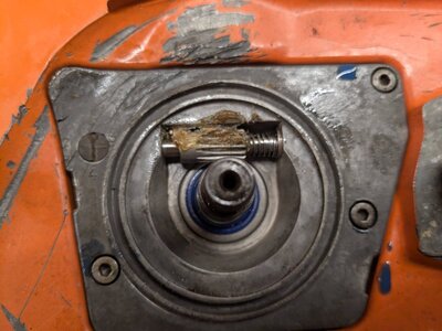
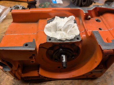
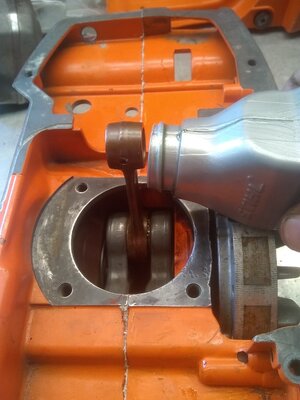
After making sure all sealing surfaces on the cases were good and clean, I laid down some dirko on the sealing surfaces of the case half, then laid the case gasket on top of that, and then laid down some more dirko onto the gasket.

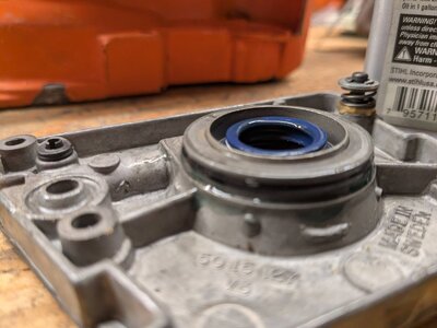
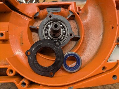
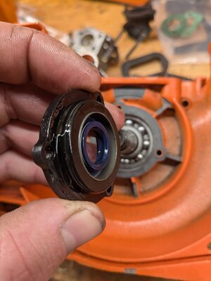
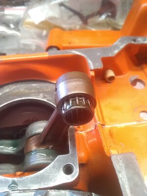
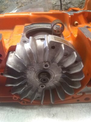
The next part is a bit tricky to get right. Use the heat gun to heat up the clutch side bearing pocket like you did the flywheel side, and then quickly slip it onto the crank/bearing. There are several things to watch out for here: Make sure the pins line up into their holes, make sure the gasket doesn't get moved or crinkled. You probably won't get to full depth before the bearing sticks into the seat. That is fine.

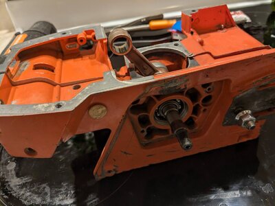
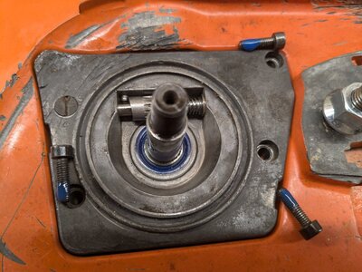
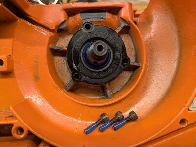
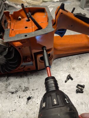
To pull it together the remainder of the way, install four case screws. Then use the heat gun again to heat the case up, while slowly working the case screws in to pull the cases together and the bearing farther into its pocket. This makes you wish you had one more hand, but it can be done. Make sure not to tighten the screws if you feel excessive resistance, and make sure the case halves are coming together evenly, and not canted in one direction or the other.

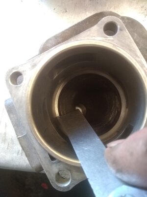
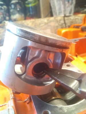
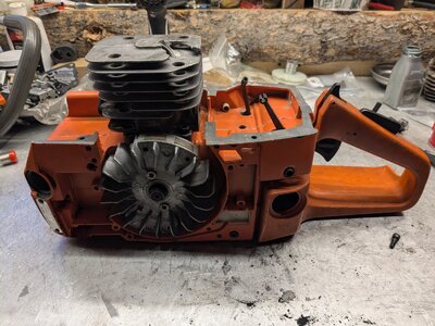
After getting the cases tightly sealed to each other, test the crank for smooth rotation. If you feel a bit of resistance, you may need to give each side a couple of light taps with a hammer. As stated before, thread a nut on (or the clutch for the reverse-thread clutch side) so that you don't mess up the threads. The crank should rotate freely with no felt resistance. Mine spun nice and smooth.

Lastly, install the front case screws (the ones that hold the dog on), and the rear case screw at the back of the carb box.
 

Attachments

  • PXL_20250218_053321016.jpg
    PXL_20250218_053321016.jpg
    217.3 KB · Views: 9
  • PXL_20250218_054737429.jpg
    PXL_20250218_054737429.jpg
    147.6 KB · Views: 7

jacktheripper

Papa Squat
GoldMember
Local time
11:59 PM
User ID
28875
Joined
Apr 5, 2024
Messages
497
Reaction score
1,841
Location
Wyoming
Country flag
Step 4: Install oil pump/seal carrier assy

On a 266, and other similar saws of the same era, Husqvarna integrated the oil pump and crank seal pocket together, and sealed the oil pump to the case with an o-ring. This o-ring is not a standard hardware store o-ring, and it should be purchased from Husqvarna as a genuine part. If you plan to re-use your o-ring, make sure that it is intact and not flattened, brittle, pinched, or stretched. Lubricate the o-ring with 2t oil when you put it on.

The crank seal must be installed at the correct depth into its pocket in the oil pump assembly. The outside face of the seal should be near flush with the outside edge of the pocket. I used a socket to tap it in. Lubricate the crank seal with 2t oil also.

Install the oiler pickup line into the crankcase. I used a Stihl-type oil filter because I did not have the old brass Husky filter. Make sure the surface where it seals against the case is cleaned up.

The oiler output hole is sealed against the case with a very small grommet. Make sure that grommet is in place on the roll pin on the pump, and that the sealing surfaces for the grommet are clean as well. See it in the top left of my picture of the back of the oil pump.

To install the oiler assy onto the case, make sure that you are not forcing the crank seal onto the crankshaft. It cannot be forced over the step on the crankshaft, so you must walk it over onto the crank. I have used a couple of different methods to do this: one is to use a piece of plastic from a zip-loc bag. Wrap it around the crank and use it as a forcing cone to walk the seal surface over the step, then slip the plastic out. The other is to *very carefully* use a tiny screwdriver to lift the lip of the seal over the edge of the crank, working around the circumference of the seal to get it completely on. Make sure not to use a sharp screwdriver if you do this, as you don't want to damage the rubber on the seal.

If at any point in the process of installing the oiler assembly, you feel excessive resistance, then stop. It should slide smoothly onto the case, and when it seats, it should push nicely into place.

Install the three screws that hold the oiler on, using blue loc-tite. Don't over tighten them. Lastly, use some grease to lubricate the oiler gear and shaft.
 

Attachments

  • PXL_20250218_060446315.jpg
    PXL_20250218_060446315.jpg
    227.5 KB · Views: 5
  • PXL_20250218_060701613.jpg
    PXL_20250218_060701613.jpg
    213.1 KB · Views: 3
  • PXL_20250218_060847436.jpg
    PXL_20250218_060847436.jpg
    128.5 KB · Views: 3
  • PXL_20250218_061040619.jpg
    PXL_20250218_061040619.jpg
    205.2 KB · Views: 3
  • PXL_20250218_061248746.MP.jpg
    PXL_20250218_061248746.MP.jpg
    159.2 KB · Views: 3

jacktheripper

Papa Squat
GoldMember
Local time
11:59 PM
User ID
28875
Joined
Apr 5, 2024
Messages
497
Reaction score
1,841
Location
Wyoming
Country flag
Step 5: Install flywheel side crank seal and carrier

On the older saws in this series (162, 266, 61, etc), Husqvarna used a plastic seal carrier on the flywheel side to hold the crank seal. It seals to the case with an o-ring as well (same part as the oiler o-ring).

This side is a bit easier to do. Tap the crank seal into the seal carrier until it bottoms out on the lip. This will be the correct depth. Lubricate the seal, lubricate the o-ring, and then slip it onto the crank and seat it into the case. Use blue loc-tite on the three screws, and tighten them.

Note that sometimes this plastic seal carrier can crack or warp. Make sure your carrier is in good shape.
 

Attachments

  • PXL_20250218_061337443.jpg
    PXL_20250218_061337443.jpg
    212.1 KB · Views: 3
  • PXL_20250218_061518430.jpg
    PXL_20250218_061518430.jpg
    95.1 KB · Views: 3
  • PXL_20250218_061623191.jpg
    PXL_20250218_061623191.jpg
    193 KB · Views: 5

jacktheripper

Papa Squat
GoldMember
Local time
11:59 PM
User ID
28875
Joined
Apr 5, 2024
Messages
497
Reaction score
1,841
Location
Wyoming
Country flag
I called it a night after that.
 

Attachments

  • PXL_20250218_062138418.jpg
    PXL_20250218_062138418.jpg
    135.2 KB · Views: 5

jacktheripper

Papa Squat
GoldMember
Local time
11:59 PM
User ID
28875
Joined
Apr 5, 2024
Messages
497
Reaction score
1,841
Location
Wyoming
Country flag
The next step is to get the top end components ready for installation. I took my new caber rings and inserted one into the cylinder in the orientation that it would be in if it was installed in the piston (make sure ring gap is on intake side and it is oriented right side up). Use your piston to push the ring into the cylinder until it is past the upper roof of the exhaust port. Then get your feeler gauges out and take a measurement. The ring gap should be about 5-12 thousandths.
 

Attachments

  • IMG_20250218_144642949_Original.jpeg
    IMG_20250218_144642949_Original.jpeg
    145.9 KB · Views: 3
  • IMG_20250218_144527938_Original.jpeg
    IMG_20250218_144527938_Original.jpeg
    172.4 KB · Views: 3
  • IMG_20250218_142613873_Original.jpeg
    IMG_20250218_142613873_Original.jpeg
    296 KB · Views: 3

jacktheripper

Papa Squat
GoldMember
Local time
11:59 PM
User ID
28875
Joined
Apr 5, 2024
Messages
497
Reaction score
1,841
Location
Wyoming
Country flag
The next step is to install the piston. Before installing, I like to drip a few drops of oil on the bearings in the bottom end. Get both main bearings, the big end rod bearing, and the wrist pin bearing. Then insert one circlip in one side of the piston carefully, so as not to damage the integrity of the wire. I like to use a pair of fine tipped needle nose pliers to hold the clip as I insert the end of the clip into its groove and then walk the other end in until it clicks. Orient the gap in the circlip so that it faces down. Some people say up, but make sure that it is not on one side or the other. Then add some oil to your wrist pin and position the piston on the rod. Make sure that the arrow on the piston crown is facing the front of the saw. This keeps the ring gap on the intake side, so as not to snag a ring. Then insert the pin and push it fully in. The last step is to install the second circlip similarly to the first. Be careful to make sure that it is fully seated in its groove. If the wrist pin is too long, or it is not pushed fully in, you may not get the circlip to seat in its groove correctly.
 

Attachments

  • IMG_20250218_144311951_Original.jpeg
    IMG_20250218_144311951_Original.jpeg
    196.7 KB · Views: 1
  • IMG_20250218_144801999_Original.jpeg
    IMG_20250218_144801999_Original.jpeg
    181.5 KB · Views: 1
  • IMG_20250218_144949780_Original.jpeg
    IMG_20250218_144949780_Original.jpeg
    174.2 KB · Views: 1

jacktheripper

Papa Squat
GoldMember
Local time
11:59 PM
User ID
28875
Joined
Apr 5, 2024
Messages
497
Reaction score
1,841
Location
Wyoming
Country flag
The next part is to check the squish. If you are using a factory cylinder and piston with a base gasket, you may decide to skip this step. If you wish to increase compression through a base gasket delete, you must check the squish in order to make sure that you don’t build yourself a “head slapper” and destroy a piston or worse. See the video for a quick demonstration.


Then, when you feel comfortable with the squish clearance, use the gasket maker of your choice (motoseal, threebond, dirko, etc) and apply a thin film to the mating surface on the case or on either side of the base gasket if you choose to use one. Slip the ring onto the piston in the correct orientation and make sure the gap is fitted correctly to the centering pin on the piston. Use some oil to lubricate the ring, the piston, and the cylinder walls. Then pinch the ring to compress it, and slip the piston into the cylinder carefully. Don’t force anything. Carefully push the cylinder down until it seats in the crankcase and insert the base bolts. Use an Allen wrench to snug the bolts, and then in a cross cross pattern, tighten them. I usually go by feel for this, but be careful not to overtighten. I use a pair of pliers to grab the Allen wrench to get the torque that is needed to tighten the bolts. Unfortunately, I am lacking decent photos of this step.
 

jacktheripper

Papa Squat
GoldMember
Local time
11:59 PM
User ID
28875
Joined
Apr 5, 2024
Messages
497
Reaction score
1,841
Location
Wyoming
Country flag
It looks like I skipped over installing the flywheel as well. I chose to do a timing advance on this saw when installing the flywheel. Advancing the timing on a saw usually gives an improved throttle response and added torque in the cut. This involves cutting a bit of metal off of the flywheel timing key with a file, which allows the flywheel to be positioned a few degrees forward of stock. I held the key in a pair of vise grips and used a flat file to remove only about 0.010” of material. You can usually get away with more, but I decided to stick with this for now. Then, put the key in the key way so the filed bit faces the right when the key way is facing up. Place the flywheel gently on the crank and rotate it counter clockwise against the key way to allow it to advance forward in timing against the newly filed surface. When in position, push it more firmly onto the taper of the crank, and install the washer and hand tighten the nut. I have found that a drop of orange or blue loc tite is helpful for added security. You can use a piece of rope stuffed in the spark plug hole as a piston stop to allow for accurate torquing of the flywheel nut with a torque wrench. Some people choose to use an impact gun, but do so at your own risk.
 

Attachments

  • IMG_20250218_143441969_Original.jpeg
    IMG_20250218_143441969_Original.jpeg
    195.9 KB · Views: 3
  • IMG_20250218_143248726_Original.jpeg
    IMG_20250218_143248726_Original.jpeg
    140.4 KB · Views: 2
  • IMG_20250218_143035545_BURST000_COVER_Original.jpeg
    IMG_20250218_143035545_BURST000_COVER_Original.jpeg
    164 KB · Views: 5

jacktheripper

Papa Squat
GoldMember
Local time
11:59 PM
User ID
28875
Joined
Apr 5, 2024
Messages
497
Reaction score
1,841
Location
Wyoming
Country flag
Next, installed the crankcase onto the handle assembly. Line up the av mounts with their respective holes, and take care not to break the throttle lever. Make sure the fuel line is routed through its hole correctly, too. Then tighten down the machine screws.
 

Attachments

  • PXL_20250219_003904438_Original.jpeg
    PXL_20250219_003904438_Original.jpeg
    345.5 KB · Views: 8
  • PXL_20250219_003938387_Original.jpeg
    PXL_20250219_003938387_Original.jpeg
    265.7 KB · Views: 8
  • PXL_20250219_004309754_Original.jpeg
    PXL_20250219_004309754_Original.jpeg
    434.1 KB · Views: 7
Top