High Quality Chainsaw Bars Husqvarna Toys Hockfire Saws

Linear measurement for port durations

paragonbuilder

Mastermind Approved!
Local time
11:20 AM
User ID
384
Joined
Jan 2, 2016
Messages
9,229
Reaction score
33,867
Location
Norwich, CT
Country flag
David thank you for this method! I was struggling to get the measurements exact but I didn't think to put a ring in the bore... That will make it much easier.
I really like the method! Im using it on my 201t thread also.


Sent from my iPhone using Tapatalk
 

Deets066

AKA Deetsey
Local time
11:20 AM
User ID
290
Joined
Dec 28, 2015
Messages
15,442
Reaction score
73,564
Location
Illinois
Country flag
You'll find out you have about 2-3 deg duration of error in your wheel measurements.
Why would the wheel measurements be off, I would think that the linear method would be handy, but how can it be as accurate unless you have the exact dimensions for con rod length. With the wheel there is no need to figure any of that.
 

David Young

Safety First !!!!!!
Staff member
Local time
11:20 AM
User ID
434
Joined
Jan 7, 2016
Messages
2,301
Reaction score
9,771
Location
vt
Country flag
And just for the record, even with exact layout numbers, I have a hard time grinding within a half degree
How does everyone put on their wheel? Drill chuck right. Ever see it not run perfectly true? It there a mirror on the wheel? Any chance parallax can play a role? How about judging when the ports are open or not. Probably close but all of these things can inject error.

Conrod length impact. Take a given Conroy length let's say for the 261 I showed ad 2 mm and subtract 2 mm. What is the change in the ex port opening.


Hope this helps deets
 

Deets066

AKA Deetsey
Local time
11:20 AM
User ID
290
Joined
Dec 28, 2015
Messages
15,442
Reaction score
73,564
Location
Illinois
Country flag
How does everyone put on their wheel? Drill chuck right. Ever see it not run perfectly true? It there a mirror on the wheel? Any chance parallax can play a role? How about judging when the ports are open or not. Probably close but all of these things can inject error.

Conrod length impact. Take a given Conroy length let's say for the 261 I showed ad 2 mm and subtract 2 mm. What is the change in the ex port opening.


Hope this helps deets
So with a 4 mm variance in the conrod length the ex. Port didn't change?

Don't get me wrong I think this method is cool and I'm glad you've shared your knowledge with us. I just tryin to wrap my head around it.
 

David Young

Safety First !!!!!!
Staff member
Local time
11:20 AM
User ID
434
Joined
Jan 7, 2016
Messages
2,301
Reaction score
9,771
Location
vt
Country flag
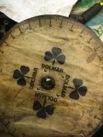
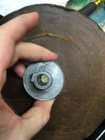
Here's my first wheel. Don't laugh too hard. :).

A wise gentleman with a deep southern accent told me get yourself a pulley with a half inch shaft. It is a little more stable than the drill chuck but is not good for larger or smaller cranks. Most are 1/2 inch though.
 

Attachments

  • image.jpeg
    image.jpeg
    145.2 KB · Views: 51

David Young

Safety First !!!!!!
Staff member
Local time
11:20 AM
User ID
434
Joined
Jan 7, 2016
Messages
2,301
Reaction score
9,771
Location
vt
Country flag
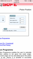
Here is the calc on transfer durations. With a 4 mm Conrod variance. Shows about .6degree variance
 

Attachments

  • image.png
    image.png
    323.5 KB · Views: 28
  • image.png
    image.png
    306.3 KB · Views: 24

srcarr52

Shop rat, backyard slice cutter.
GoldMember
Local time
11:20 AM
User ID
522
Joined
Jan 12, 2016
Messages
4,088
Reaction score
26,854
Location
Iowa City
Country flag
Why would the wheel measurements be off, I would think that the linear method would be handy, but how can it be as accurate unless you have the exact dimensions for con rod length. With the wheel there is no need to figure any of that.

And just for the record, even with exact layout numbers, I have a hard time grinding within a half degree

The wheel measurements are prone to error because you can only be so accurate with visually spotting the piston to the port opening. Large chamfers, port entrance angle, and piston rock all effect the crank angle, then add the inaccuracy of reading the wheel and you can have quite some error band.

I did a study a while back with a wheel. I did multiple measurements not looking at the wheel until I was ready to read it, and taking my hands off the everything in between measurements to remove any muscle memory. I found that my measurements on port opening blew almost 3 degrees, which would be 6 deg duration.

1/2 degree duration on most saws is around 0.005" of an inch. I modified a dial caliper so it can catch the port edge and measure to the squish band. With this I can get within 0.005" pretty easy. In fact, I usually get within 0.002" from one trans port to the other, from the factory I've seen them as far off at 0.030".

I always measure the conrod length but as shown by David 4mm or 0.157" only changed didn't change the port timing as much as you would think. The error in this decreases towards TDC and BDC as the angle of the rod decreases, so the most error will be on the transfer ports.

There are some online apps that will calculate port timing from measured heights. I made an excel sheet to do all the calculations. All of the equations you'll need are in A. Graham Bells book, "Two Stroke Performance Tuning." As well there are a few examples that you can double check you sheet with.
 

Danders

Well-Known OPE Member
Local time
8:20 AM
User ID
139
Joined
Dec 24, 2015
Messages
76
Reaction score
144
Location
Forest Grove, OR
Country flag
[QUOTE="srcarr52, post: 41870, ...All of the equations you'll need are in A. Graham Bells book, "Two Stroke Performance Tuning." As well there are a few examples that you can double check you sheet with.[/QUOTE]

The spreadsheet sounded like a good idea, and I was eventually able to replicate the formulas for exhaust and intake duration. The whole radians/degrees thing was sure a pain but eventually Google came through with a solution. The main downside to me is that the wheel readings are logically pretty straightforward to understand, provided you've got tdc set correctly. The formulas right now are a mind-numbing mess to me by themselves, and I have only a very rough feel for how a measurement should translate into a circular measurement of degrees. I am looking forward to trying the measurement process though.
 

srcarr52

Shop rat, backyard slice cutter.
GoldMember
Local time
11:20 AM
User ID
522
Joined
Jan 12, 2016
Messages
4,088
Reaction score
26,854
Location
Iowa City
Country flag
[QUOTE="srcarr52, post: 41870, ...All of the equations you'll need are in A. Graham Bells book, "Two Stroke Performance Tuning." As well there are a few examples that you can double check you sheet with.

The spreadsheet sounded like a good idea, and I was eventually able to replicate the formulas for exhaust and intake duration. The whole radians/degrees thing was sure a pain but eventually Google came through with a solution. The main downside to me is that the wheel readings are logically pretty straightforward to understand, provided you've got tdc set correctly. The formulas right now are a mind-numbing mess to me by themselves, and I have only a very rough feel for how a measurement should translate into a circular measurement of degrees. I am looking forward to trying the measurement process though.[/QUOTE]

Yes, all sine functions are in radians in Excell (I.E. COS(), SIN(), TAN())

In Excell

degree_value = radian_value * 180/PI()
radian_value = degree_value * PI()/180

For example piston height from the squish band is:

PH = SBC + S/2 + RL - S/2*COS(THETA * PI() / 180) - SQRT( RL^2 - (S/2)^2 * SIN( THETA * PI() / 180) ^2 )

where:
PH = Piston distance from squish band
SBC = squish band clearance
S = Stroke
RL = rod length
THETA = crank angle where 0 deg is at TDC.
 

lwhaples

Pinnacle OPE Member
Local time
11:20 AM
User ID
898
Joined
Feb 16, 2016
Messages
660
Reaction score
1,225
Location
Vt
Sounds like some head scratching needs to happen,a lot of good info.
 

paragonbuilder

Mastermind Approved!
Local time
11:20 AM
User ID
384
Joined
Jan 2, 2016
Messages
9,229
Reaction score
33,867
Location
Norwich, CT
Country flag
The spreadsheet sounded like a good idea, and I was eventually able to replicate the formulas for exhaust and intake duration. The whole radians/degrees thing was sure a pain but eventually Google came through with a solution. The main downside to me is that the wheel readings are logically pretty straightforward to understand, provided you've got tdc set correctly. The formulas right now are a mind-numbing mess to me by themselves, and I have only a very rough feel for how a measurement should translate into a circular measurement of degrees. I am looking forward to trying the measurement process though.

Yes, all sine functions are in radians in Excell (I.E. COS(), SIN(), TAN())

In Excell

degree_value = radian_value * 180/PI()
radian_value = degree_value * PI()/180

For example piston height from the squish band is:

PH = SBC + S/2 + RL - S/2*COS(THETA * PI() / 180) - SQRT( RL^2 - (S/2)^2 * SIN( THETA * PI() / 180) ^2 )

where:
PH = Piston distance from squish band
SBC = squish band clearance
S = Stroke
RL = rod length
THETA = crank angle where 0 deg is at TDC.
1cb2ab01462078082c15ed156069a500.jpg


Sent from my iPhone using Tapatalk
 
Last edited:

Al Smith

Here For The Long Haul!
Local time
11:20 AM
User ID
537
Joined
Jan 14, 2016
Messages
6,401
Reaction score
14,243
Location
North western Ohio
Country flag
On that wheel deal I have adapters to go on whatever ever size crankshaft thread I'm using .They don't wibble wobble .

I guess I'm just old school stupid .I just peek in through the plug hole with a bright LED pen light and look at the wheel to see where it's at .On the other hand I might have the cylinder off three or 4 times to get it right .

Don't get me wrong because it's good info but in my case the time you figure the angle of the dangle with the rod at a certain degree of rotation and all that goobley gook my head would hurt .
 

Danders

Well-Known OPE Member
Local time
8:20 AM
User ID
139
Joined
Dec 24, 2015
Messages
76
Reaction score
144
Location
Forest Grove, OR
Country flag
For example piston height from the squish band is:

PH = SBC + S/2 + RL - S/2*COS(THETA * PI() / 180) - SQRT( RL^2 - (S/2)^2 * SIN( THETA * PI() / 180) ^2 )

where:
PH = Piston distance from squish band
SBC = squish band clearance
S = Stroke
RL = rod length
THETA = crank angle where 0 deg is at TDC.

Trying to get my head around this and not succeeding. At tdc, it has to return a value equal to sbc doesn't it? After 90 degrees of rotation, wouldn't the measurement equal half the stroke plus sbc? I don't have a working formula, I'm just trying to troubleshoot.
 

srcarr52

Shop rat, backyard slice cutter.
GoldMember
Local time
11:20 AM
User ID
522
Joined
Jan 12, 2016
Messages
4,088
Reaction score
26,854
Location
Iowa City
Country flag
Trying to get my head around this and not succeeding. At tdc, it has to return a value equal to sbc doesn't it? After 90 degrees of rotation, wouldn't the measurement equal half the stroke plus sbc? I don't have a working formula, I'm just trying to troubleshoot.

Yes, at TDC (THETA=0) PH = SBC, because COS(0) = 1 SIN(0) = 0.

Now at THETA=90, COS(90)=0, SIN(90)=1, therefor PH = SBC + S/2 + RL - SQRT( RL^2 - (S/2)^2)
This is because the crank and rod are forming a right triangle where the height of the triangle is SQRT( RL^2 - (S/2)^2)

At THETA=180, COS(180)=-1, SIN(180)=0, so PH = SBC + S
 
Top