High Quality Chainsaw Bars Husqvarna Toys

A home-made Capacitor Discharged Ignition unit for an old saw

chy_farm

Pinnacle OPE Member
Local time
6:40 AM
User ID
3497
Joined
Jul 3, 2017
Messages
397
Reaction score
2,126
Location
Yokohama, JAPAN
-------- The value of C3 is faulty, must be 0.8 microfarad.---------
What I have acquired from my experiment,
http://opeforum.com/threads/a-home-...nition-unit-for-an-old-saw.11409/#post-589785
it seems that there are some rules between the capacitance of this part and the speed of spin.

When I see these rules, it seems that there is not so much difference between 0.8uF and 1.0uF in regard to this capacitor unless you spin the motor higher than e.g. say 10,000rpm.
 
Last edited:

mgr1

Super OPE Member
Local time
10:40 PM
User ID
2365
Joined
Dec 27, 2016
Messages
456
Reaction score
1,021
Location
Belgium
Country flag
The bosh ignition is original a 0,8 microfarad. If you replace this by a 1microfarad and use it on a ported saw than you notice a difference. There need to be more time to charge the capacitor like you have tested.

@chy_farm After all you did i nice job on your homemade ignition. With your knowledge you can make NLA ignition coils.
 
Last edited:

chy_farm

Pinnacle OPE Member
Local time
6:40 AM
User ID
3497
Joined
Jul 3, 2017
Messages
397
Reaction score
2,126
Location
Yokohama, JAPAN
The bosh ignition is original a 0,8 microfarad. If you replace this by a 1microfarad and use it on a ported saw than you notice a difference. There need to be more time to charge the capacitor like you have tested.

@chy_farm After all you did i nice job on your homemade ignition. With your knowledge you can make NLA ignition coils.
@mgr1 Good morning, you are right. I think I will use 0.47uF capacitor for my McCulloch 795 project now going, this motor is to spin at nearly 13,500 when it does her job.
 

Al Smith

Here For The Long Haul!
Local time
5:40 PM
User ID
537
Joined
Jan 14, 2016
Messages
6,095
Reaction score
13,457
Location
North western Ohio
Country flag
That's asking a lot of a stock reed valve engine .They could wind up a souped up kart engine that fast but they didn't last that long between either a rebuild or blowing the engine up .
 

chy_farm

Pinnacle OPE Member
Local time
6:40 AM
User ID
3497
Joined
Jul 3, 2017
Messages
397
Reaction score
2,126
Location
Yokohama, JAPAN
Good morning @Al Smith , @mgr1 ,
tried some simulation to the Dolmar 119 circuit this morning.
The original design mgr1 posted here is this;
dolmar-119-cdi-png.109920


The same one with the simulator LT-Spice is this;
Simu_Pulses.jpg
The Exciter coil and the primary coil are both built on the same iron core or laminate core, this mean they generate pulsive current that come alternatively in a short time like e.g. once in 10milisecond. This is equivalent to the spin speed of 6000 rpm. So these current are given by V1 and V2 in this simulation.
The letters beginning with 'PWL(0 0m 2.0m ...)' seen at the top of this pic shows the construction of the simulating pulse given to this circuit.

Instead of applying a thyristor I used an equivalent two-transistor circuit for it, which consists of PNP and NPN transistors.

To begin with this, let's see the default status;
Simu_Pulses_Blank.jpgIt's all blank.

Now see how this V1 gives the current;
Simu_Pulses_Excitor.jpgI set the peak voltage to 100V but perhaps this value is a little too high, better lower it to 30V or so.

Then added the current given from the primary coil.
Simu_Pulses_Excitor_and_Prim.jpg

Added the current from the secondary;
Simu_Pulses_Excitor,Prim_and_Secd.jpg
Chy
 
Last edited:

legdelimber

Pinnacle OPE Member
Local time
5:40 PM
User ID
8391
Joined
Jan 14, 2019
Messages
562
Reaction score
1,321
Location
N.C.
Country flag
Been reading this and trying to get my head wrapped back around things.
Many years ago, I learned enough to know what was causing the dark line to crawl up the screen of an old CRT television set and a few other minor problems.

The capacitor charge rise time has always seemed like a way to build a rev limiter. Chy-farm has shown it to happen.
(Thank you chy-farm for all of that work!)
i.e. perhaps charge a cap that triggers a separate gated device, which bleeds off the current to ground, rather than into the high tension side of the coil.

That said:
I can't help but look at these circuits and think of needing to think of resonances (that alter current flow) and band pass stuff.
Think of analog audio & speaker crossovers.
I'm thinking of a high pass filter as a rev limiter.
Or how about another circuit to slightly bleed a small amount off of the charge, so as to slow the advance curve?

I read a little bit about transformers when power inverters were still a new thing on the market.
Thus, my money is on that "foot" shape of the, three leg Stihl armature, as having a strong affect on the advance curve.

...and lastly, Yes, the phrase "a smattering of ignorance on many things" would cover me well.
so please forgive me the rambling, half finished thoughts here.
Much, much more in my head but clinical ADD makes it hard to get things typed out in one posting.
 
Last edited:

legdelimber

Pinnacle OPE Member
Local time
5:40 PM
User ID
8391
Joined
Jan 14, 2019
Messages
562
Reaction score
1,321
Location
N.C.
Country flag
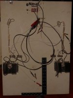
This was nearly all from the junk bins, but here's my transformer test board, from my inverter tinkering moments.
Inverters prices came down faster than I could scrounge things and learn.
So it sits in a corner now. 25 years worth of dust on it.

I'd love to see any news on the ignition projects!
 

Attachments

  • Free running oscillator Transformer test board .JPG
    Free running oscillator Transformer test board .JPG
    97.1 KB · Views: 19
Last edited:

Junk Meister

Pinnacle OPE Member
Local time
4:40 PM
User ID
1674
Joined
Aug 10, 2016
Messages
710
Reaction score
2,000
Location
Nebraska
Country flag
but he does not know I am an chainsaw enthusiast, lol.
Never assume to know what someone hasn't told you what they do know about you They may be trying to be polite:rolleyes:
Your articles are way above my level of experience But Thanks for the challenges :confused:
 

Stihl working Hard

Is it Friday yet
Local time
5:40 AM
User ID
802
Joined
Feb 6, 2016
Messages
34,308
Reaction score
109,217
Location
Perth Australia
Prior to soldering parts on the board, better have some checks on the performance of the circuit with a bread-board;
View attachment 106746
A small green capacitor seen at the top center in above is not an auto-use, means it's not a high-voltage use. The voltage of the current this primary coil needs is not less than 150 volts in its operation, so we have to choose ones for auto-use, like the one I pick up from Shiduki's line-ups.

In my first trial video,

Homemade CDI unit for Partner R417T(I), a test run!

I tried to leave this small green capacitor on this bread-board (I should not do this though), which got extremely hot in a short time of this trial use.
So if you want to try, keep in mind that you should chose the right one! or it will get exploded.

Chy
Riverting thread Chy you’ve been holding out on us my friend :campeon:
 
Top