High Quality Chainsaw Bars Husqvarna Toys Hockfire Saws

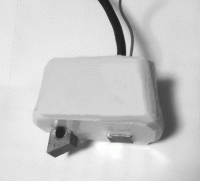
A home-made Capacitor Discharged Ignition unit for an old saw

chy_farm

Pinnacle OPE Member
Local time
2:14 AM
User ID
3497
Joined
Jul 3, 2017
Messages
397
Reaction score
2,126
Location
Yokohama, JAPAN

chy_farm

Pinnacle OPE Member
Local time
2:14 AM
User ID
3497
Joined
Jul 3, 2017
Messages
397
Reaction score
2,126
Location
Yokohama, JAPAN
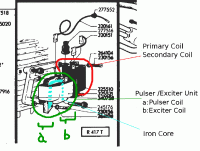
The outlook of this ignition unit originally installed for her is this;
IPL_Coils.gif
From above view we know there are two coils,

one for the primary-secondary coil which generates high voltage for the spark,

and

another for the exciter and pulser coil, the former of which works for giving induction current to the primary coil, the latter gives timing signal to the thyristor.

The original simple CDI unit had have been installed in between (a) coil and (b) coil painted in green in the above view, which was found broken when she came to me.
 
Last edited:

chy_farm

Pinnacle OPE Member
Local time
2:14 AM
User ID
3497
Joined
Jul 3, 2017
Messages
397
Reaction score
2,126
Location
Yokohama, JAPAN
In between and around these
(a) coil/ pulser coil
and
(b) coil/ exciter coil,
epoxy was filled, and in this the broken CDI unit has been sitting. This epoxy was so hard and caused some small breakage to the primary coil (a) when I tried removing this epoxy off.

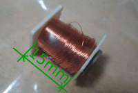
But rewinding job was not very difficult, first try look for some good used small coil from a junk computer around you, drag out one end of the copper wire from the coil.
Magnet_Wire.gif
Keep in mind that the surface of the wire of this kind is most always plated with insulation-fibers.

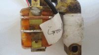
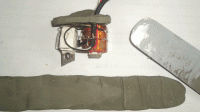
Wind it around the iron core to form the pulser coil (one in the right), and wrap it with a strip of paper with some glue.
Pulser_Exciter_Coil_0.gif
 

chy_farm

Pinnacle OPE Member
Local time
2:14 AM
User ID
3497
Joined
Jul 3, 2017
Messages
397
Reaction score
2,126
Location
Yokohama, JAPAN
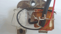
The other side;
Pulser_Exciter_Coil_1.gif

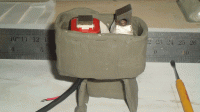
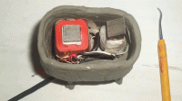
Next step is filling 'something good' around these coils. I used silicone rubber as a temporary experimental use, but you might as well use epoxy.

Some clay is useful for casting silicone rubber.
Pulser_Exciter_Coil_2.gif

Cover these coils thoroughly with clay and see the horizontal level.
Pulser_Exciter_Coil_3.gif
 

chy_farm

Pinnacle OPE Member
Local time
2:14 AM
User ID
3497
Joined
Jul 3, 2017
Messages
397
Reaction score
2,126
Location
Yokohama, JAPAN
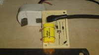
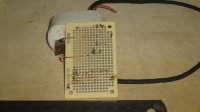
Prior to soldering parts on the board, better have some checks on the performance of the circuit with a bread-board;
Electric_Parts.gif
A small green capacitor seen at the top center in above is not an auto-use, means it's not a high-voltage use. The voltage of the current this primary coil needs is not less than 150 volts in its operation, so we have to choose ones for auto-use, like the one I pick up from Shiduki's line-ups.

In my first trial video,

Homemade CDI unit for Partner R417T(I), a test run!

I tried to leave this small green capacitor on this bread-board (I should not do this though), which got extremely hot in a short time of this trial use.
So if you want to try, keep in mind that you should chose the right one! or it will get exploded.

Chy
 

chy_farm

Pinnacle OPE Member
Local time
2:14 AM
User ID
3497
Joined
Jul 3, 2017
Messages
397
Reaction score
2,126
Location
Yokohama, JAPAN
[What does the size of capacitor mean in CDI ?]

In a capacitor discharged ignition, a capacitor sits before the primary coil means a lot. It accumulates enough electricity to make a good spark. A moment after it gets full with electricity it wants to start emitting the electricity. So we give this capacitor a chance to start this action by using a thyristor, a semiconductor. This emitting action is discharge that causes higher voltage current to the secondary coil.

My interest was 'what the size of this capacitor should be?', so I tried some experiments on this.
 

chy_farm

Pinnacle OPE Member
Local time
2:14 AM
User ID
3497
Joined
Jul 3, 2017
Messages
397
Reaction score
2,126
Location
Yokohama, JAPAN
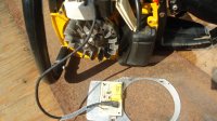
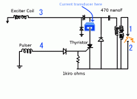
A current transducer I have posted above, I quote it here again;
cdi_circuit_current_2-gif.106495

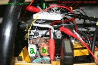
shows the movements of these 1; charging current to the capacitor and 2; discharging current from the capacitor.

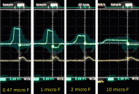
The sizes of the capacitors I used here are 0.47 microFarads, 1.0 microFarads, 2.0 microFarads, and 10 microFarads. Below is a result;
Charging_Voltages_to_Capacitor_failure.gifHorizontal division shows 10 milliseconds, while vertical division 5.0 volts.
For each time the starter rope was pulled with full speed.
 

chy_farm

Pinnacle OPE Member
Local time
2:14 AM
User ID
3497
Joined
Jul 3, 2017
Messages
397
Reaction score
2,126
Location
Yokohama, JAPAN
Good afternoon Steve, thank you for comment, I think it's one of the greatest fun-thing to do that job on saws.
I am wanting to do this on my on-going old Mac 795 project as you know, and for a moded Dolmar 7900 too.
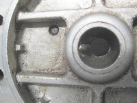
This 7900 has been installed with an over-sized piston and ring kit, and the flywheel timing was moded/reduced a couple of degrees to retard, see a pic;
7900_flywheel_mod_2deg_01.JPG

This mod was not so bad, but better should be a 'programed timing'.

Chy
 
Last edited:

chy_farm

Pinnacle OPE Member
Local time
2:14 AM
User ID
3497
Joined
Jul 3, 2017
Messages
397
Reaction score
2,126
Location
Yokohama, JAPAN
Being back to [What does the size of capacitor mean in CDI ?], see the pic that shows time spans when the capacitor being charged. We see a comparison between the two in the center below;
charging_voltages_to_capacitor_failure-gif.106763

The charging time for each are
1 micro Farads : 6 milliseconds,
2 micro Farads : 8 milliseconds.

When a motor spins at 10,000rpm, it takes 6 milliseconds to make a spin, and this motor needs a capacitor which volume is less than 1 micro Farads,
and
when a motor spins at 7,500rpm, it takes 8 milliseconds to make a spin, and this motor needs a capacitor which volume is less than 2 micro Farads,

So these mean that when we want to have a motor run faster than 7,500 rpm, this motor needs a capacitor which volume is less than 2 micro Farads, or more specifically we need much smaller capacitor.

This is what my second video
Homemade CDI for Partner R417T (II)
means.
 

Al Smith

Here For The Long Haul!
Local time
12:14 PM
User ID
537
Joined
Jan 14, 2016
Messages
6,391
Reaction score
14,198
Location
North western Ohio
Country flag
Good evening Al, a man of electrical engineering, have not seen you in the CSCF these days, nice to see you here, and what is your alternative then?
Chy
It obviously works .My lack of understanding is how does the gate circuit of the SCR work? I understand how the fly back circuit works on the cap it's just how does it flow through the diodes .
Maybe there's is something I'm over looking but in my mind the diodes are reverse biased .Unless they are zener diodes which wasn't specified .Nice job by the way .
As for the cap size I suppose the rise time of the cap would have to calculated from an RLC circuit but it's been literally decades since I've done those calculations .
 
Top