High Quality Chainsaw Bars Husqvarna Toys Hockfire Saws

261 M-Tronic - What makes it tick.....

plcnut

Jesus is LORD
Local time
2:44 AM
User ID
917
Joined
Feb 20, 2016
Messages
1,428
Reaction score
8,896
Location
Mansfield, Missouri
Country flag
As I wrap my head around this, I have discovered the current hardware methods being used to Advance timing on any electronic ignition saw will produce the same results as an M-Tronic.

Advancing the timing by means of a modified hardware key (lets say 5 degreese), will in all affect only do just that...
The internal chip / software only has one method of knowing TDC and that's thru the trigger sensor (on the Sparkplug side of the coil) and the flywheel.

As a result, if you take a stock M-Tronic, connect a timing light and take measurements at 1000, 4000, and 6000 RPM's, then do the same for a modified, 5 degree advanced saw, the timing light at those same speeds will be advanced by exactly 5 degrees.

There is no other sensor / method for the saws electronic ignition to know something has changed except for the trigger sensor.

Now if a software change could done to set a 5 degree advance, the saw would need to make 2 maybe 3 revolutions on Startup so as to Power Up the chip, read the trigger sensor, and make the preprogrammed adjustment.

On the other hand, some type of mechanical movement of the coil pack as the throttle is being used, could result in a faster responding acceleration because the coil would be physically advancing and retarding the timing....

Just throwing it out there.... Something that came into my head and needed to verbalize it....
LOL

Thinking out loud here:

I don't think that a mechanical adjustment will ever be faster than what the software adjustments will be. The program in the chip is not being run inside an OS, so the speed will be very high. In the old saws, the points will actually float at high rpm's, but the electronics in a new saw are faster than the mechanics in the old ones.

The timing curve built into the chip has to be dynamic, because otherwise, advancing the timing via the key would effectively raise the rev limiter, but it does not.

@breese, have you seen the Stihl manual for the pre Mtronic coils? It even has photographs of the coils internals as well as a description of the principal of operation.
 

breese

Pinnacle OPE Member
GoldMember
Local time
2:44 AM
User ID
3719
Joined
Aug 2, 2017
Messages
393
Reaction score
1,563
Location
Chicagoland, Illinois
Country flag
have you seen the Stihl manual for the pre Mtronic coils? It even has photographs of the coils internals as well as a description of the principal of operation.
I have a lot of different manuals and documentation and have found nothing showing the internal of the coil.
 

plcnut

Jesus is LORD
Local time
2:44 AM
User ID
917
Joined
Feb 20, 2016
Messages
1,428
Reaction score
8,896
Location
Mansfield, Missouri
Country flag
We recently deployed an automation system with a 50 microsecond response time using a RTOS (real time operating system) over EtherCAT. That equals 20,000 scans per second.
Even a small microchip is potentially capable of being much faster.

I would also not be surprised if there was an accelerometer built into one of the chips. This could be used as a knock sensor as well as providing feedback for misfires.
 

breese

Pinnacle OPE Member
GoldMember
Local time
2:44 AM
User ID
3719
Joined
Aug 2, 2017
Messages
393
Reaction score
1,563
Location
Chicagoland, Illinois
Country flag
The thing is, right now everything is based on Throttle and RPM.
The electronic ignition in the saw's take the RPM information (again this is from the coil trigger side) and applies an algorithm built into the chip and make a decision on what the advancement in timing should be.
This is the same procedure to limit RPM.

With no physical "Bounce" (like with points), the system has the ability to be faster and more accurate to a degree.
It does not take into account (such as in an auto or truck) the load on the engine or air fuel mixture entering or leaving the engine.

As a result, loading the chain (pushing hard into log) is in effect putting the saw into a rich setting ( as some have indicated as fuel coming out of the exhaust).

Is the code / chip capable of knowing the Throttle is at WOT, not that I have seen. Even the newer ones with the carb solenoid does not register back to the chip any information except for what appears to be an Ohm reading of sorts indicting the solenoids current position. I opened the solenoid yesterday. There is No Chip within it. so there must be another way of communication happening along with power across this 1 wire system.

The diode within the throttle section for startup was a clue to something other than a true master and slave chip ID capable system.

On the original subject.... Throttle indicates RPM, and my nature indicates advancement in timing as per the set conditions within the chip coding.
 

plcnut

Jesus is LORD
Local time
2:44 AM
User ID
917
Joined
Feb 20, 2016
Messages
1,428
Reaction score
8,896
Location
Mansfield, Missouri
Country flag
I have never looked at a Stihl Mtronic system before, but the Huskies do have a TPS.
As far as the solenoid is concerned, it could be using either a PWM or a variable voltage to the solenoid to control the flow. Either way, the chip could be reading the coils reactance etc to know the coils position (the same technology that is used for sensorless vector control).
 

plcnut

Jesus is LORD
Local time
2:44 AM
User ID
917
Joined
Feb 20, 2016
Messages
1,428
Reaction score
8,896
Location
Mansfield, Missouri
Country flag
The diode within the throttle section for startup was a clue to something other than a true master and slave chip ID capable system.
According to the patent that was posted earlier, the 1 wire system uses a time slot for each device to talk. There is a large disruption that happens each time the spark is triggered. Each device looks at this disruption, and calculates it's 'talk time'.
For example:
Let's say the the engine is running at 1000 rpm.
There are 60,000ms per minute, divided by 1000 rotations per minute, equals 60ms per revolution.
If the spark disruption takes 10ms, then we have 50ms for the devices to talk.
If you had 3 devices, then each of them would get ~16.6ms to talk. The chip already knows that the carbureter (for example) gets to talk first, so it listens to the carb for 16ms, it then listens to the power switch for 16ms, and then listens to the coil 16ms. The amount of time that each device is allowed to talk varies every revolution based upon the time between disruptions. It can only work because the rpm's can only change a (relatively) small amount between each disruption.
Each device on the LIN calculates it's time slot during every revolution.
The document also said that there was a dead-time built in around each devices talk time to limit the amount of interference.

I have not finished reading the patent document yet, but this is my understanding of how the system works.

Please feel free to correct my errors :)
 

breese

Pinnacle OPE Member
GoldMember
Local time
2:44 AM
User ID
3719
Joined
Aug 2, 2017
Messages
393
Reaction score
1,563
Location
Chicagoland, Illinois
Country flag
Picture is on page 12.
Thanks for the document...
While it has some good information, it is a basic document in that while it gives some descriptions of how the digital ignition works, it is an information document on old systems... Nothing with the newer technology.

The picture shown in the document is a standard ignition.
Old Style Coil.jpg

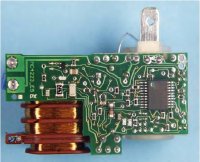
The newer coils are much more complicated and as you can see, the board has been expanded over the coil, and the traces are much larger for specific power handling.
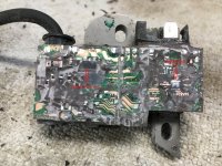
Excuse how bad the board looks but this is the result of removing the coating that seals the coil pack.
Many hrs of work...
Coil-006a.jpg
 

breese

Pinnacle OPE Member
GoldMember
Local time
2:44 AM
User ID
3719
Joined
Aug 2, 2017
Messages
393
Reaction score
1,563
Location
Chicagoland, Illinois
Country flag
I have not finished reading the patent document yet, but this is my understanding of how the system works.
Exactly except, its a first come, first serve....
Without a known Slave by an on-board chip (yes the assumption was every device had a chip and hardcoded ID found in LIN systems), I know the carb solenoid does not have a chip.
There-for it has to be an OHM or type reading by the coil chip to know what each device is.

As a reference, when the Start Switch is on, it makes contact with a diode that has a Known Ohm reading, there-by informing the coil chip we are now in "Start Mode" and when the pull cord is pulled, the chip activates, see's the setting of the Start Switch, and sets up the timing perimeters.

With this knowledge, any other External device will function the same.
Internally there is the possibility that a specific line on the chip is dedicated to (lets say) a temp probe.
This temp probe (being a direct connection) would Not Need that disruption to communicate.
 

breese

Pinnacle OPE Member
GoldMember
Local time
2:44 AM
User ID
3719
Joined
Aug 2, 2017
Messages
393
Reaction score
1,563
Location
Chicagoland, Illinois
Country flag
Is the wire that runs from the coil to the solenoid the same wire that also ties to the start/stop switch?
Yes

I am running on the (dangerous) assumption that this is a 1 wire daisy chain system. Is that the case?
For the 261 saw, the solenoid and the start switch are BUT the switch then makes a connection to the diode.
It will take me a few to find the diagram

As for any other devices on other saws or in the future, I would assume this daisy chain would not be the case.
 

nohoff

professional flusher
Local time
9:44 AM
User ID
4033
Joined
Sep 11, 2017
Messages
478
Reaction score
2,007
Location
Germany
If the Solenoid is PWM based it only needs the ohm reading for the Start/Stop switch.
In the diagnostic mode you hear the diagnostic system triggering the solenoid. And it meassures the ohms on the solenoid and start switch.

Breese tell me what i should measure and i will do it on every M-Tronix (except MS 661).
 

breese

Pinnacle OPE Member
GoldMember
Local time
2:44 AM
User ID
3719
Joined
Aug 2, 2017
Messages
393
Reaction score
1,563
Location
Chicagoland, Illinois
Country flag
With the start/stop off, what is the voltage while running and what is the ohm's reading when not running.

With the start/stop on, same question.....
 

nohoff

professional flusher
Local time
9:44 AM
User ID
4033
Joined
Sep 11, 2017
Messages
478
Reaction score
2,007
Location
Germany
Ok i'll try tomorrow MS 261 and the MS 462 if it's back.
So we have the values for M-Tronic Ver. I and II
 
Top