High Quality Chainsaw Bars Husqvarna Toys

Lets build a Husqvarna 262XP, SCARR style!

srcarr52

Shop rat, backyard slice cutter.
GoldMember
Local time
4:25 AM
User ID
522
Joined
Jan 12, 2016
Messages
3,943
Reaction score
26,001
Location
Iowa City
Country flag
Since I received a 262 cylinder and carb in the fundraiser a little while back I decided to pull this 262 project out of the moth balls.

Sorry, no tear down pictures. There wasn't much to see but the pound of grease and sawdust it left on my bench.

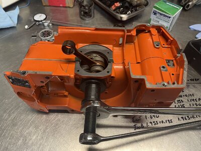
So we'll start here with the clean case and new nachi open bearings.
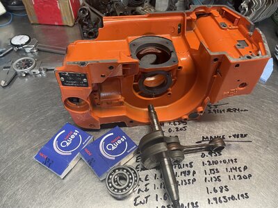
IMG_4061.JPG

Wipe the rust preventative off the bearings or they'll stick on you. Since this saw has a blind bearing pocket on the PTO side and a through hole on the flywheel side we'll start on the PTO side.

A little heat from a map gas torch gets us this far. Heat the case 1/2, slip the bearing in. Wait for it to heat soak and add a little more heat to the inner race to slip the crank in. Then hold the other bearing with channel locks while you heat it and then slip it onto the flywheel side of the crank. While this cools it's a good time to clean the case bolts up.
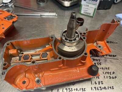
IMG_4063.JPG
 

srcarr52

Shop rat, backyard slice cutter.
GoldMember
Local time
4:25 AM
User ID
522
Joined
Jan 12, 2016
Messages
3,943
Reaction score
26,001
Location
Iowa City
Country flag
Next I use one of the many Husqvarna crank tools to pull the flywheel side bearing in. I also heat the case some to make it easier. Once the cases are close enough I install the case bolts loosely to keep everything lined up and keep the gasket in place.

IMG_4064.JPG

Usually with the crank puller there is no need to tap the crank to free up the bearings, if you used the bolts to pull the case together you'll need to hit the PTO side crank snout to loosen the bearings a bit.
 

srcarr52

Shop rat, backyard slice cutter.
GoldMember
Local time
4:25 AM
User ID
522
Joined
Jan 12, 2016
Messages
3,943
Reaction score
26,001
Location
Iowa City
Country flag
I have two cylinders at my disposal. One is a KS non-decomp, the other is a Mahle decomp.

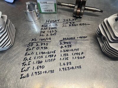
Many know that I like to do things differently. I like to take measurements from the port edges to the squish band and from those and a few other measurements I can calculate the port timing. No degree wheel error, no having to set the cylinder back on the chassis to check port timing.

IMG_4060.JPG

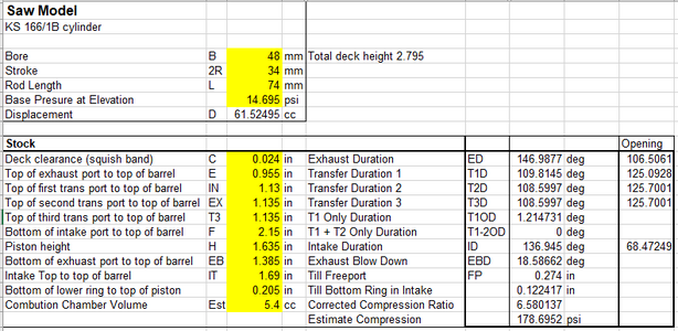
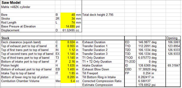
So we plug all this mumbo jumbo into the formulas and we get the timing numbers. I normally think in durations because it makes sense, larger the number the more time it's open. I've included the inversely related, counter intuitive, opening numbers for you all that like those measurements.

KSTiming.png

MahleTiming.png

As you can see the port timing is pretty similar, both open the intake side of the transfer ports first which I like to do the opposite.

I've chosen to go with the Mahle cylinder just for the decomp button!
 

Canadian farm boy

“Normal” people scare me.
GoldMember
Local time
4:25 AM
User ID
309
Joined
Dec 29, 2015
Messages
7,829
Reaction score
49,354
Location
Ontario, Canada
Country flag
Great thread Shaun.

It’s been a while since I played around inside a 262 cylinder but I’m curious if you timed both the pto and FW side transfers?
For some reason lm wanting to think that stock they are timed differently by like 2*.
I could be thinking of a different saw or it could have been a fluke jug I’m thinking about.
 

srcarr52

Shop rat, backyard slice cutter.
GoldMember
Local time
4:25 AM
User ID
522
Joined
Jan 12, 2016
Messages
3,943
Reaction score
26,001
Location
Iowa City
Country flag
Great thread Shaun.

It’s been a while since I played around inside a 262 cylinder but I’m curious if you timed both the pto and FW side transfers?
For some reason lm wanting to think that stock they are timed differently by like 2*.
I could be thinking of a different saw or it could have been a fluke jug I’m thinking about.

I always do, in the measurements picture you can see the measurements are longer (less duration) for the PTO side on the KS cylinder and shorter (more duration) for the Mahle cylinder. On this saw 0.005" of the port height is ~0.6° opening, ~1.2° duration.

So:
The KS opened the flywheel side first 0.6° before the PTO, yielding an additional 1.2° duration.
The Mahle opened the PTO side first 1.8° before the flywheel, yielding an additional 3.6° duration.
 

srcarr52

Shop rat, backyard slice cutter.
GoldMember
Local time
4:25 AM
User ID
522
Joined
Jan 12, 2016
Messages
3,943
Reaction score
26,001
Location
Iowa City
Country flag
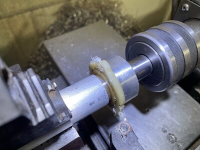
The flywheel side seal carriers are notorious for warping and causing an air leak. I measured the depth of the bearing in the case minus the step protruding into the case from the carrier and I had 0.010" of room to drop the carrier in further. So I decided to skim cut just the face of the carrier to make it flat again. I made a quick mandrel to reference the ID of the seal pocket and traped it with the live center.

IMG_4070.JPG

Really it's just the bolt wings that deform so I've probably just trued it up to factory specs.
 

srcarr52

Shop rat, backyard slice cutter.
GoldMember
Local time
4:25 AM
User ID
522
Joined
Jan 12, 2016
Messages
3,943
Reaction score
26,001
Location
Iowa City
Country flag
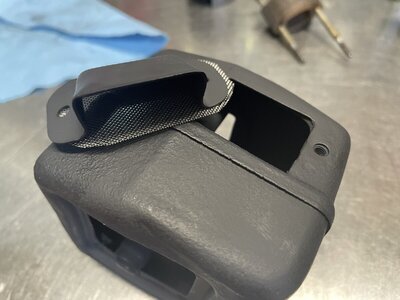
For the muffler I've fitted a Dyno Joe large deflector to the OEM bolt locations but I've made the area for the screen as large as possible.

IMG_4094.JPG


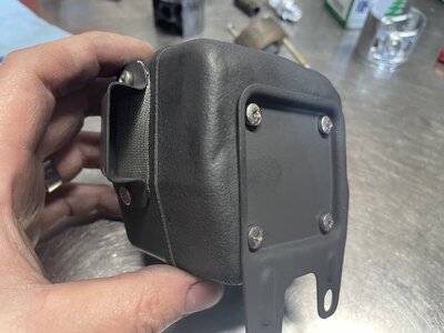
Installed with some stainless screws. Pretty clean look with plenty of flow.

IMG_4095.JPG
 

srcarr52

Shop rat, backyard slice cutter.
GoldMember
Local time
4:25 AM
User ID
522
Joined
Jan 12, 2016
Messages
3,943
Reaction score
26,001
Location
Iowa City
Country flag
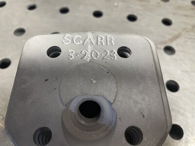
I've decided to take 0.060" from the squish. I didn't measure the chamber after the machine work so 4.7cc is an estimate. Here are the numbers I've decided on. Now I grind will I reach the measurements.

MahleNewTiming.png

I like to use a layout dye marker on the exhaust port and scribe some clean lines to grind to. Here is the ex port about mid rough in. I don't think I'll push it all the way to my upper line.

IMG_4079.JPG
 

srcarr52

Shop rat, backyard slice cutter.
GoldMember
Local time
4:25 AM
User ID
522
Joined
Jan 12, 2016
Messages
3,943
Reaction score
26,001
Location
Iowa City
Country flag
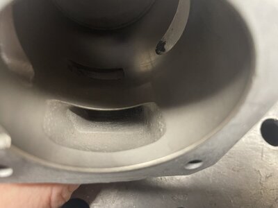
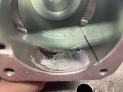
These cylinders have a cast in bump in the already large lower transfers. Maybe they were too good in testing and they had to add the bump to choke them down a little.

IMG_4096.JPG


We'll get rid of that, get rid of the step into the port and open it up a bit more. I like the lowers to have a straight shot at the top corner. This is just roughed in, it will be more refined later.

IMG_4080.JPG
 

srcarr52

Shop rat, backyard slice cutter.
GoldMember
Local time
4:25 AM
User ID
522
Joined
Jan 12, 2016
Messages
3,943
Reaction score
26,001
Location
Iowa City
Country flag
On these older saws where the exhaust port comes out at a 90° to the bore I like to create a little dip in the exhaust port floor so the exhaust gets to come out of the cylinder at a little more of an angle before it makes the turn for the muffler.

IMG_4089.JPG

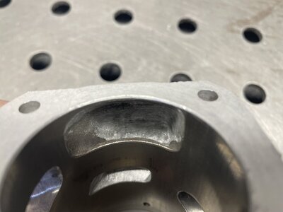
And the cylinder side, nothing too special here. Just widened it a touch and raised it to 152° duration or 104° opeing.

IMG_4088.JPG

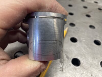
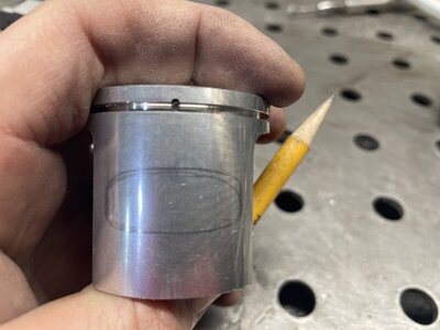
I like to use a mechanical pencil to trace the port onto the piston so I can study the shape and how much skirt is left to seal the port. I'll lightly scribe a flat line with a dial caliper for reference lines so I can see how evenly shaped the port is or how much arch I have in the roof. You can see I made a few iterations on the flywheel side of the ex port as there are a few extra trace lines there.

That got a little bigger!

IMG_4093.JPG
 

srcarr52

Shop rat, backyard slice cutter.
GoldMember
Local time
4:25 AM
User ID
522
Joined
Jan 12, 2016
Messages
3,943
Reaction score
26,001
Location
Iowa City
Country flag
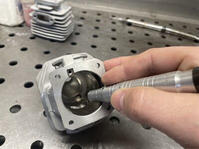
Again on the intake I used a pencil to trace the port. I did reshape the port some on the lower right of the trace to make it more symetrical but I didn't retrace it.

IMG_4092.JPG


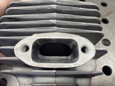
I didn't add any duration other than what was added from the machine work. Then I roughed up the port with some 40 grit cartridge rolls.

IMG_4087.JPG
 

srcarr52

Shop rat, backyard slice cutter.
GoldMember
Local time
4:25 AM
User ID
522
Joined
Jan 12, 2016
Messages
3,943
Reaction score
26,001
Location
Iowa City
Country flag
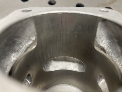
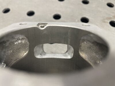
I worked over the transfers to open the exhaust side first, opening a little over 1° before the intake side. Then I shape the intake with a sharp point of entrance at a bit steeper angle than the exhaust side.

IMG_4086.JPG

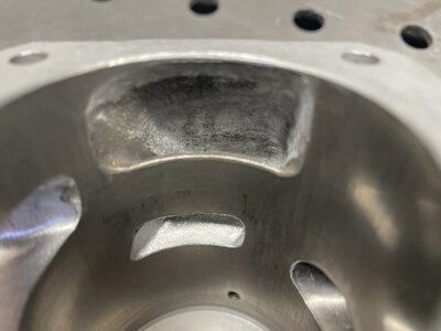
And now you can see how the lowers almost have direct access to the top corner, just a little gradual curve over the whole outside wall. Most of the work is all done on the exhaust side of the transfer port as that is where the majority of the flow should come from.

IMG_4085.JPG
 

srcarr52

Shop rat, backyard slice cutter.
GoldMember
Local time
4:25 AM
User ID
522
Joined
Jan 12, 2016
Messages
3,943
Reaction score
26,001
Location
Iowa City
Country flag
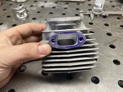
Now here comes the sad part. I was gasket matching the muffler and realized I don't have the heat shield and a few other small bits. So parts are on order and I'll just have to work on what I can until they show up.
 

srcarr52

Shop rat, backyard slice cutter.
GoldMember
Local time
4:25 AM
User ID
522
Joined
Jan 12, 2016
Messages
3,943
Reaction score
26,001
Location
Iowa City
Country flag
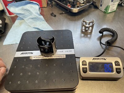
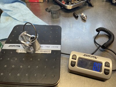
The original ring is stuck in the piston and I can't get it out to weigh just the piston but I suspect it's significantly lighter than the meteor. After a fair amount of grinding on the meteor piston and even the pin I managed to make the whole setup a bit lighter than the OEM.

IMG_4075.JPG

IMG_4078.JPG
 
Top