

- Local time
- 10:58 PM
- User ID
- 25695
- Joined
- Dec 13, 2022
- Messages
- 53
- Reaction score
- 220
- Location
- Hamburg, NY
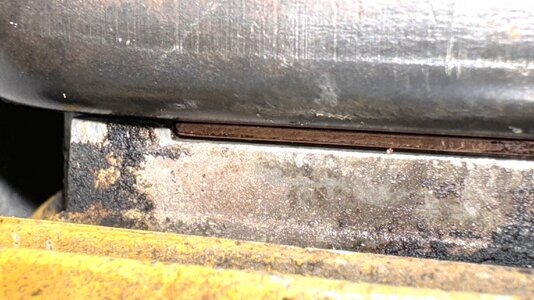
I understand that but the muffler bottoms out on the raised pedestals not the ridge. I would think that they would have gone flat with a ridge (crush) point on a independent flat surface and not raise the muffler off it, that is my question.Hi Jeff,
I would assume that small raised line cast into the cylinder is to create a pressure or crush point on a soft gasket. My Printing company screen prints silicone beading on gaskets for local gasket companies and this is used to help seal better than a gasket alone by creating this high pressure "ridge".
I don't see a step so much as a raised "row" of material that would essentially do the same thing.
Brian Genrich
Old Saw Shop
Not a biggie it was the 70's which I remember vaguely

ps Any suggestions for a fuel line ? Was gonna try tygon and grommet method but plug and play would be nice
Attachments
Last edited:


 , Nathan