High Quality Chainsaw Bars Husqvarna Toys

372 Cylinder head.

Darryll

Well-Known OPE Member
Local time
11:10 PM
User ID
1886
Joined
Sep 23, 2016
Messages
73
Reaction score
132
Location
New Zealand
Country flag
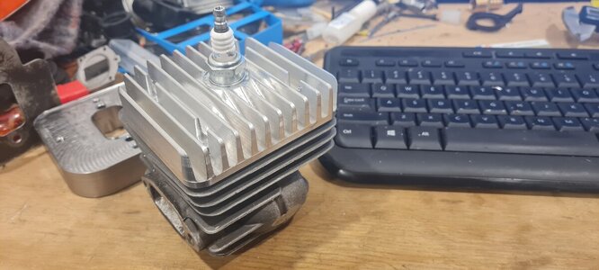
Of late I have been playing around with cylinder heads on my 372 and CNC machining them with cooling fins and sealing them with FKM O rings and torture testing it. Almost surprisingly the saw never got hot after several tank's of back back cutting with a 36" buried into wood. So I'm quietly hoping this may help me unlock a bit more potential reliably. It was a 52mm Hyway and pretty conservative numbers and the saw had an awesome spread of power, certainly better than anything I have built before. It felt very aggressive to run and handled the 36" better than my stock 592. As a side note to be able to remove the head about as quick as pulling the plug has been great for monitoring. Thanks to the modern Marvels of todays world I can design the head with a given compression ratio and machine it rather precisely. For the record 10.5:1 is too much. Even with the plug centered and a tight squish it rattled its self almost to death with 91 fuel, I don't want the hassle of having 98 on site. I think somewhere around 10:1 is the sweet spot. If I lived in the states I'd probably reach out to Dyno Joe to test it for me.

I've also been playing with lengthening the intake track and running the 660 carb on it. This absolutely picked up a fair bit in the very top end responding a bit like a powerband. Certainly some sort of resonance going on. It would be nice if it was a few thousand revs lower but I'll take that as a win for now. I have put a fair bit of work into this so far and started to get some real results. There is a fair bit left to get this sorted but once I get the air filter etc worked out and 3D printed I think there is some potential there to be had. The goal here is to build myself a 9-10+ hp 372 that can be used everyday.

I'd also like to make my own piston. If anyone has already been down that road I like to here about it.
 

Attachments

  • 20230920_124424.jpg
    20230920_124424.jpg
    104 KB · Views: 72
Last edited:

stumpyfine

Well-Known OPE Member
Local time
11:10 PM
User ID
2632
Joined
Feb 13, 2017
Messages
25
Reaction score
110
Location
Cambridge New Zealand
Country flag
Hello Darryl looks really good
I am up in Cambridge not far from the Naki experimenting with some similar ideas just fitted a dio head to a 440/460 hybrid along with a 660 carb. will try and get some pics up in the next day or so.
 

Darryll

Well-Known OPE Member
Local time
11:10 PM
User ID
1886
Joined
Sep 23, 2016
Messages
73
Reaction score
132
Location
New Zealand
Country flag
Its good to hear others are into doing this in NZ. I have done some porting for others but I'm more interested in finding the limits of a reliable work saw. These detachable cylinder heads need more testing etc but first impressions are that it just might be possible. I'm revising the design to angle the plug like a stock head to fit in the stock plastics.

I'd be keen to see what you are up to and your thoughts on your results. I like the 70cc class of saw for size and for the few days that Hyway lasted it proved some really good power can be made.
 

srcarr52

Shop rat, backyard slice cutter.
GoldMember
Local time
7:10 AM
User ID
522
Joined
Jan 12, 2016
Messages
3,943
Reaction score
26,001
Location
Iowa City
Country flag
Most use corrected compression ratio for 2 strokes, which uses only the trapped volume above the export. 8:1 is about the highest I go for a work saw, that's around 220 psi cranking compression at sea level.

I have cut cooling fins into heads on race saws and it does make them run more consistent.
 

Darryll

Well-Known OPE Member
Local time
11:10 PM
User ID
1886
Joined
Sep 23, 2016
Messages
73
Reaction score
132
Location
New Zealand
Country flag
Most use corrected compression ratio for 2 strokes, which uses only the trapped volume above the export. 8:1 is about the highest I go for a work saw, that's around 220 psi cranking compression at sea level.

I have cut cooling fins into heads on race saws and it does make them run more consistent.
Is my calculation wrong?

Trapped Volume 48.8cc + Combustion chamber 5.4cc = 54.2cc/5.4 = 10.03:1

A possible difference is that my combustion chamber is measured by Fusion in Cad. I'd consider that to be pretty precise. It does not include the squish band clearance and as you know that can account for a fair volume. Nor to my mind should we include that volume to our calculation as in theory if you have your squish set right there is little too no clearance between the top of the piston and the squish band while running. That said I guess none of us actually have no clearance so maybe I should allow .1mm in my calc which would lower it a small amount.

If we were to use Jennings as a bench mark and we accept that we are designing reasonably optimum combustion chamber shapes he suggests 9:1 in Moto X racing with a max of 9.5:1. This of course includes the use of a tuned pipe which has a supercharging effect. I have deliberately pushed the ratio up to find the limit and as I have never experienced detonation previously when I did the other day at 10.5:1 I figured that was our absolute limit or maybe I should say my absolute limit as I understand not everyone is using my method. Given my results roughly lined up with Jennings I figured I was in the ball park. Plus fuel of today etc and dare I say it I don't think Jennings had the ability to do what we can do today with computers. cad and CNC milling machines. Not to be seen as cherry picking information Jennings does recommend a lower ratio for road racing with a squish band ratio of about 40%. But once again that is partly due to the pipe configuration which we don't have.

All of that said is 10:1 the optimum ratio? I don't know, I have some saws with 9 and 9.5:1 that run great. I believe that top end performance is helped as Jennings states with a lesser ratio. I know well you run higher cranking pressures and I guess for the same reason we all do as it helps the saws pull.

The main reason I wanted to build the head was to change the ratio of squish band to see if there are any benefits. Currently I'm around 46% in a cut squish. If I build my own head I can experiment with 60%

My goal here is to design and build the optimum head and having the freedom to port how I want too and not be governed by the stock cylinder. My first test was to see if it would over heat and maintain a seal. It seems to have passed that test, now the fun begins.

I know you have pushed the limits, if you have any thoughts or suggestions I'd be happy to try them.
 
Last edited:

stumpyfine

Well-Known OPE Member
Local time
11:10 PM
User ID
2632
Joined
Feb 13, 2017
Messages
25
Reaction score
110
Location
Cambridge New Zealand
Country flag
Here's some pics of the DIO head on the 440 hybrid, I put a 2mm spacer under the cylinder to bring the exhaust and transfers level with the top of the piston at BDC. Also fitted a 660 carb, straightened and expanded the intake boot with a piece of copper tube inside. Will cut the fins some more to get the cover to fit.have only just got running but seems to run well.
20231010_193019.jpg20231010_193026.jpg20231010_193042.jpg

the idea I have is to optimise the transfers then alter the exhaust and intake to suit. Am looking at fitting an alloy or steel plate to the top of the exhaust port if necessary.
 

Darryll

Well-Known OPE Member
Local time
11:10 PM
User ID
1886
Joined
Sep 23, 2016
Messages
73
Reaction score
132
Location
New Zealand
Country flag
That looks awesome. You are on the same thought path as myself with regard to getting the timing where you want it. I too like to have the piston line up with the bottom of the ports. How have you sealed it?
 

stumpyfine

Well-Known OPE Member
Local time
11:10 PM
User ID
2632
Joined
Feb 13, 2017
Messages
25
Reaction score
110
Location
Cambridge New Zealand
Country flag
Thanks, currently I have the head recessed to fit like a cap over the cylinder,no gasket required, if that dosent work I am thinking of trying a copper washer type gasket.
As far as the ports go I have noticed that the stihl 660 cylinders have the top of exhaust port too high and the bottom of the transfers too low by quite varying amounts? and the clone cylinders seem to have copied the worst ones.
I checked an oem 064 and it was way better, so explains why they out performed the 660.
 

srcarr52

Shop rat, backyard slice cutter.
GoldMember
Local time
7:10 AM
User ID
522
Joined
Jan 12, 2016
Messages
3,943
Reaction score
26,001
Location
Iowa City
Country flag
Is my calculation wrong?

Trapped Volume 48.8cc + Combustion chamber 5.4cc = 54.2cc/5.4 = 10.03:1

A possible difference is that my combustion chamber is measured by Fusion in Cad. I'd consider that to be pretty precise. It does not include the squish band clearance and as you know that can account for a fair volume. Nor to my mind should we include that volume to our calculation as in theory if you have your squish set right there is little too no clearance between the top of the piston and the squish band while running. That said I guess none of us actually have no clearance so maybe I should allow .1mm in my calc which would lower it a small amount.

If we were to use Jennings as a bench mark and we accept that we are designing reasonably optimum combustion chamber shapes he suggests 9:1 in Moto X racing with a max of 9.5:1. This of course includes the use of a tuned pipe which has a supercharging effect. I have deliberately pushed the ratio up to find the limit and as I have never experienced detonation previously when I did the other day at 10.5:1 I figured that was our absolute limit or maybe I should say my absolute limit as I understand not everyone is using my method. Given my results roughly lined up with Jennings I figured I was in the ball park. Plus fuel of today etc and dare I say it I don't think Jennings had the ability to do what we can do today with computers. cad and CNC milling machines. Not to be seen as cherry picking information Jennings does recommend a lower ratio for road racing with a squish band ratio of about 40%. But once again that is partly due to the pipe configuration which we don't have.

All of that said is 10:1 the optimum ratio? I don't know, I have some saws with 9 and 9.5:1 that run great. I believe that top end performance is helped as Jennings states with a lesser ratio. I know well you run higher cranking pressures and I guess for the same reason we all do as it helps the saws pull.

The main reason I wanted to build the head was to change the ratio of squish band to see if there are any benefits. Currently I'm around 46% in a cut squish. If I build my own head I can experiment with 60%

My goal here is to design and build the optimum head and having the freedom to port how I want too and not be governed by the stock cylinder. My first test was to see if it would over heat and maintain a seal. It seems to have passed that test, now the fun begins.

I know you have pushed the limits, if you have any thoughts or suggestions I'd be happy to try them.

The squish clearance adds to the chamber volume, which is the denominator, and it significantly effect your calculation.

With the bore and d (distance of cylinder) in mm the volume in cc is:
v = PI * (bore/2)^2 * d / 1000

In my experience a smaller squish band width always seems to run better.
 

Darryll

Well-Known OPE Member
Local time
11:10 PM
User ID
1886
Joined
Sep 23, 2016
Messages
73
Reaction score
132
Location
New Zealand
Country flag
Thanks for the formula but I already have that in my spread sheet to calculate the volume along with the formula to calculate the distance to TDC from top of EX giving me (d).

Out of curiosity I run the numbers through my spread sheet on the stock Hyway 52mm. EX 100 and I got 9.32:1 when I added a squish of .5mm it dropped to 8.1:1. So if you were using oil and a syringe I can see how you would arrive at a number like 8:1 on a stock cylinder, in fact potently lower as they generally have more clearance stock. I think I'll continue to measure my ratios as I have as it is more correct and certainly when machining with the CNC far more precise. I can see no good reason to add the squish clearance to the volume. Jennings went to a great deal of effort using Perspex and injecting the oil through a hole on an upturned head to prevent surface tension in order to avoid including the squish clearance. This makes sense to me.

You must be cranking your saws to get them to 220psi? Mine are around the 160-180 finished, that said I haven't actually used the tester for some years preferring the consistency I get machining the head instead. I never checked that Hyway but it was possibly in that 220 region as you sure as hell knew you were starting it.

I jumped from 10:1 to 10.5:1 so who knows at what point it would have started pre igniting. At 10:1 I had no sign of it. At the end of the day that is our limiting factor. I never played with the timing as it was easier to recut the head.

Yes that is my observation also with regard the squish band width. When we cut the squish with a lath we end up with the square edge and the saws feel harsh to my mind. When I started cutting the combustion chambers with the CNC and I could uniform the chamber and radius the edge they felt silky smooth. I'm not articulate enough to explain that better sorry. But I suspect you know exactly what I mean. My motivation to try a wider squish with a properly formed chamber is to see if as Jennings suggests it will help with the mid range. Also with the saws being particularly over square to use a small band width you end up with a shallow dome meaning a greater distance for the flame front, which likely explains why we notice the saws run smoother. The Hyway I just did was not particularly pleasant but it certainly was stout. If you have already been down this path and can save me the trouble please let me know.

I very rarely post in here but it is good to kick around differing views. I appreciate your thoughts, it gives me cause to think.
 
Last edited:

stumpyfine

Well-Known OPE Member
Local time
11:10 PM
User ID
2632
Joined
Feb 13, 2017
Messages
25
Reaction score
110
Location
Cambridge New Zealand
Country flag
That looks awesome. You are on the same thought path as myself with regard to getting the timing where you want it. I too like to have the piston line up with the bottom of the ports. How have you sealed it?
I have just checked out VW,porsche and Yanmar air cooled sealing methods. there is some helpful info on the net
 

Darryll

Well-Known OPE Member
Local time
11:10 PM
User ID
1886
Joined
Sep 23, 2016
Messages
73
Reaction score
132
Location
New Zealand
Country flag
I have just checked out VW,porsche and Yanmar air cooled sealing methods. there is some helpful info on the net
I'll have a look. The best O Rings I could find here in NZ were rated to 200C. They showed absolutely no sine of heat and sealed perfectly. I have since got these FKM O rings and they are rated to 260C I'm pretty confident they will last a good while. I brought a heap of them and its so easy to replace them so I could careless if they do fail every 100hrs or so. I'd say that my machined head sitting on the machined cylinder did the line share of the work. There was a very small amount of evidence that the gas leaked to the O Ring in two places. Further more I could see the head was bedding into the cylinder and in few more hours I'd say it would be pretty much a perfect seal. Those surfaces were milled not turned in a lath. If you are turning them its likely you will have a better finish than I got.

After all the work you have done I hope it goes like hell.

You lost me when you were talking about putting a plate in the exhaust? what was that about?
 

srcarr52

Shop rat, backyard slice cutter.
GoldMember
Local time
7:10 AM
User ID
522
Joined
Jan 12, 2016
Messages
3,943
Reaction score
26,001
Location
Iowa City
Country flag
Thanks for the formula but I already have that in my spread sheet to calculate the volume along with the formula to calculate the distance to TDC from top of EX giving me (d).

Out of curiosity I run the numbers through my spread sheet on the stock Hyway 52mm. EX 100 and I got 9.32:1 when I added a squish of .5mm it dropped to 8.1:1. So if you were using oil and a syringe I can see how you would arrive at a number like 8:1 on a stock cylinder, in fact potently lower as they generally have more clearance stock. I think I'll continue to measure my ratios as I have as it is more correct and certainly when machining with the CNC far more precise. I can see no good reason to add the squish clearance to the volume. Jennings went to a great deal of effort using Perspex and injecting the oil through a hole on an upturned head to prevent surface tension in order to avoid including the squish clearance. This makes sense to me.

You must be cranking your saws to get them to 220psi? Mine are around the 160-180 finished, that said I haven't actually used the tester for some years preferring the consistency I get machining the head instead. I never checked that Hyway but it was possibly in that 220 region as you sure as hell knew you were starting it.

I jumped from 10:1 to 10.5:1 so who knows at what point it would have started pre igniting. At 10:1 I had no sign of it. At the end of the day that is our limiting factor. I never played with the timing as it was easier to recut the head.

Yes that is my observation also with regard the squish band width. When we cut the squish with a lath we end up with the square edge and the saws feel harsh to my mind. When I started cutting the combustion chambers with the CNC and I could uniform the chamber and radius the edge they felt silky smooth. I'm not articulate enough to explain that better sorry. But I suspect you know exactly what I mean. My motivation to try a wider squish with a properly formed chamber is to see if as Jennings suggests it will help with the mid range. Also with the saws being particularly over square to use a small band width you end up with a shallow dome meaning a greater distance for the flame front, which likely explains why we notice the saws run smoother. The Hyway I just did was not particularly pleasant but it certainly was stout. If you have already been down this path and can save me the trouble please let me know.

I very rarely post in here but it is good to kick around differing views. I appreciate your thoughts, it gives me cause to think.

With the syringe and windshield washer fluid (much less messy than oil) method I make a plate that seals against the squish band. So it only measures the chamber volume. So I have to add the volume from the squish clearance to the total chamber volume to get the correct compression ratio.

You can take this further since the compression ratio is essentially the Ideal gas law excluding the pressures:

pv=nrt, nrt is constant, so p1*v1 = p2*v2

Solving for p2, p2 = p1*v1/v2, note here p1 is the atmospheric pressure at your altitude.

Compression ratio is v1/v2.

So if you have your compression ratio you can calculate the maximum cranking compression which assumes no loss through the rings and no added chamber volume by the test gauge. The formula gets a little more tricky because compression gauges are "gauge pressure" meaning they have an offset of atmospheric pressure.

V2 must be everything left in the cylinder at TDC which is the chamber volume + squish clearance volume.

220psi it with a gauge pulling it over normally. I rarely go over that as it's a chore to pull over, but with smaller bores you can get away with higher compression.

Again, all your previously calculations where you omitted the squish clearance volume are incorrect.

I always blend off the sharp corner after cutting a squish band, not a huge radius but I break the corner. I don't like the idea of the sharp corner tripping the flame front.
 
Last edited:

Darryll

Well-Known OPE Member
Local time
11:10 PM
User ID
1886
Joined
Sep 23, 2016
Messages
73
Reaction score
132
Location
New Zealand
Country flag
With the syringe and windshield washer fluid (much less messy than oil) method I make a plate that seals against the squish band. So it only measures the chamber volume. So I have to add the volume from the squish clearance to the total chamber volume to get the correct compression ratio.

You can take this further since the compression ratio is essentially the Ideal gas law excluding the pressures:

pv=nrt, nrt is constant, so p1*v1 = p2*v2

Solving for p2, p2 = p1*v1/v2, note here p1 is the atmospheric pressure at your altitude.

Compression ratio is v1/v2.

So if you have your compression ratio you can calculate the maximum cranking compression which assumes no loss through the rings and no added chamber volume by the test gauge. The formula gets a little more tricky because compression gauges are "gauge pressure" meaning they have an offset of atmospheric pressure.

V2 must be everything left in the cylinder at TDC which is the chamber volume + squish clearance volume.

220psi it with a gauge pulling it over normally. I rarely go over that as it's a chore to pull over, but with smaller bores you can get away with higher compression.

Again, all your previously calculations where you omitted the squish clearance volume are incorrect.

I always blend off the sharp corner after cutting a squish band, not a huge radius but I break the corner. I don't like the idea of the sharp corner tripping the flame front.
I agree with everything you have written but I cant see why you would want to include squish clearance. I'm very interested in your thinking here. More than happy to change my position but need to understand why. I do see why you should include excess squish clearance.

Using the 372 as an example and a saw I had a bit to do with I've experience lite piston contact between .4mm and .6mm clearance depending on the condition of the saw. I set mine to .5 run them and check and I can only assume I have about .1mm excess clearance. Most certainly I should include that in the ratio. No argument there. If I was honest till this conversation with you I had not considered doing so but I will add that to my spread sheet and for certain that will knock a few points off my predicted ratio.

I don't want to be seen as making a big deal out of a small point but I'm in a bit of a unique position of being able to build a saw in Fusion 360 and push a green button. So this detail matters to me. I'm pretty convinced that I make more power with my mill than I do with the grinder. I'm also very convinced that combustion design matters a lot. I have noticed a significant improvement in my saws since I've been playing around with this stuff.
 

Darryll

Well-Known OPE Member
Local time
11:10 PM
User ID
1886
Joined
Sep 23, 2016
Messages
73
Reaction score
132
Location
New Zealand
Country flag
I always blend off the sharp corner after cutting a squish band, not a huge radius but I break the corner. I don't like the idea of the sharp corner tripping the flame front.
Yep! I put a 4mm radius on that edge.

The 500I has an interesting chamber and there is no denying it runs well stock....well at least on top. Huge radius. I have not measured it properly but I'd say its in the region of 10mm. Small squish band and rather tight dome. I have not done the 500 before but it is next on my list to Cad up.

What are your thoughts on that design?
 

srcarr52

Shop rat, backyard slice cutter.
GoldMember
Local time
7:10 AM
User ID
522
Joined
Jan 12, 2016
Messages
3,943
Reaction score
26,001
Location
Iowa City
Country flag
I agree with everything you have written but I cant see why you would want to include squish clearance. I'm very interested in your thinking here. More than happy to change my position but need to understand why. I do see why you should include excess squish clearance.

Using the 372 as an example and a saw I had a bit to do with I've experience lite piston contact between .4mm and .6mm clearance depending on the condition of the saw. I set mine to .5 run them and check and I can only assume I have about .1mm excess clearance. Most certainly I should include that in the ratio. No argument there. If I was honest till this conversation with you I had not considered doing so but I will add that to my spread sheet and for certain that will knock a few points off my predicted ratio.

I don't want to be seen as making a big deal out of a small point but I'm in a bit of a unique position of being able to build a saw in Fusion 360 and push a green button. So this detail matters to me. I'm pretty convinced that I make more power with my mill than I do with the grinder. I'm also very convinced that combustion design matters a lot. I have noticed a significant improvement in my saws since I've been playing around with this stuff.

Changing squish clearance changes the compression you’d get with a gauge. Should is not change your compression ratio calculation as well?
 

Darryll

Well-Known OPE Member
Local time
11:10 PM
User ID
1886
Joined
Sep 23, 2016
Messages
73
Reaction score
132
Location
New Zealand
Country flag
Changing squish clearance changes the compression you’d get with a gauge. Should is not change your compression ratio calculation as well?
Arrr yes I understand your thinking now.

Yes and no.

When static testing compression I'd say for sure you are also testing the full value of the clearance hence giving a lower reading. If somehow you could do a static test at 11,00rpm I'm pretty confident it would be a somewhat higher reading (for a few reasons actually). At 11,00rpm its a different story as the clearance is reduced to a minimal amount and I believe in my builds that to be approximately .1mm and you make a good point in that I should be including that value. To my mind when we get it right there should be no Clarence at full rpm if we are doing our job right. I have seen in the carbon deposits when my builds are right on the ragged edge. In those I'd argue there is no gap at full rpm. Work saw builds I like to leave .2mm or .7mm build clearance allowing .4-.5mm movement at full rpm. I hope I have articulated that in a way that makes sense?

In a stock saw I'd say that is quite a large number from the squish band that needs to be added as they are about 1-1.2mm.

You have raised some interesting points and I'm thinking either compression ratio and or compression tests offer little more than a bench mark as we can make a pretty solid argument either way. I will include an amount of about .1mm for the sake of being as correct as I can be but I think more importantly is that what ever I do I do consistently. The reality is my offering of ratios that work for me have little value to others on the grounds that its so bloody hard to properly measure the value in the cylinder head and your methodology sounds great. I guess that's why most do compression tests. The CNC has given me an alternative that is pretty dead nuts and saves me the hassle of actually measuring it.

The last thing I want to do is confuse any topic's so I will refrain from offering any technical information in the future. I'll just show pretty pictures.
 

srcarr52

Shop rat, backyard slice cutter.
GoldMember
Local time
7:10 AM
User ID
522
Joined
Jan 12, 2016
Messages
3,943
Reaction score
26,001
Location
Iowa City
Country flag
Arrr yes I understand your thinking now.

Yes and no.

When static testing compression I'd say for sure you are also testing the full value of the clearance hence giving a lower reading. If somehow you could do a static test at 11,00rpm I'm pretty confident it would be a somewhat higher reading (for a few reasons actually). At 11,00rpm its a different story as the clearance is reduced to a minimal amount and I believe in my builds that to be approximately .1mm and you make a good point in that I should be including that value. To my mind when we get it right there should be no Clarence at full rpm if we are doing our job right. I have seen in the carbon deposits when my builds are right on the ragged edge. In those I'd argue there is no gap at full rpm. Work saw builds I like to leave .2mm or .7mm build clearance allowing .4-.5mm movement at full rpm. I hope I have articulated that in a way that makes sense?

In a stock saw I'd say that is quite a large number from the squish band that needs to be added as they are about 1-1.2mm.

You have raised some interesting points and I'm thinking either compression ratio and or compression tests offer little more than a bench mark as we can make a pretty solid argument either way. I will include an amount of about .1mm for the sake of being as correct as I can be but I think more importantly is that what ever I do I do consistently. The reality is my offering of ratios that work for me have little value to others on the grounds that its so bloody hard to properly measure the value in the cylinder head and your methodology sounds great. I guess that's why most do compression tests. The CNC has given me an alternative that is pretty dead nuts and saves me the hassle of actually measuring it.

The last thing I want to do is confuse any topic's so I will refrain from offering any technical information in the future. I'll just show pretty pictures.

If you're going to bother to calculate the compression ratio, you might as well be as accurate as possible. Errors on the chamber side on the equation can change the ratio significantly.

For instance, on a stock clone 372 which has a chamber volume of ~6.7cc. Changing the squish clearance from the factory 0.043" to 0.020" changes the compression ratio from 5.3:1 to 6.25:1. That has an exhaust port height of 0.985" from the squish band. The volume of the squish clearance area goes from 2.14cc to 1cc.

So you can imagine as the chamber gets smaller, the volume from the squish clearance becomes more important.

You also have to remember that the displaced volume of the piston is the exhaust port height from the squish band minus the squish clearance. So the squish clearance also has an effect on the numerator.

You need clearance because the piston rocks, and it rocks more as it wears. This is why with smaller bores, or taller pistons, you can run tighter squish clearance.

I measure chamber volume all the time... it's not that hard. Cut a Lexan plate to cover the squish band with a hole in it... fill with syringe till all the bubbles are out. This also includes the small volume you get from the spark plug recess around the porcelain.

And actually, the squish clearance is increased at 11k rpm because the piston has a lot of pressure on top of it, compressing the rod, piston, bearings. If it was spinning from an outside source with no spark plug, then yes it would be stretching the rod and such. But when a two-stroke engine is running the rod force is never very large into the tension direction because of the compression and combustion forces.
 
Top