


You are using an out of date browser. It may not display this or other websites correctly.
You should upgrade or use an alternative browser.
You should upgrade or use an alternative browser.
MCCULLOCH The official McCulloch thread
- Thread starter Frank bierce
- Start date
- Local time
- 7:42 AM
- User ID
- 714
- Joined
- Jan 28, 2016
- Messages
- 2,817
- Reaction score
- 18,947
- Location
- Dike, Iowa
Not a 3-25, the front wrap handle does not match the 3-25 style. Most likely a 4-30 or perhaps a 47.
3-25

4-30

47

Mark
3-25
4-30
47
Mark

RickZ
Active OPE Member
- Local time
- 6:42 AM
- User ID
- 10585
- Joined
- Sep 28, 2019
- Messages
- 13
- Reaction score
- 22
- Location
- New Mexico
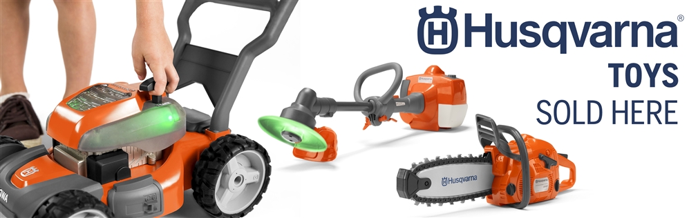
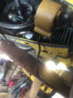
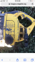
Here is a couple better pictures. There are 4 wires that are disconnected. One from a condenser below the flywheel, two wires coming from the handle and another from under the flywheel. The larger condenser above the coil had a connection on each side. I’m just not sure what goes where. Crossing my fingers that the diagram Steve has will have what I need.I do not have a wiring diagram .The picture is unclear what is or might be attached and where but I assume under a screw on the brush holder .You might try a continuity check to see if one brush might already connected to ground .If the other doesn't show continuity to ground it should the where the hot wire goes .BTW I have never seen the workings of a battery start saw,Mac or otherwise if there ever was another company making them .Keep in mind this is all for naught unless it has s a working battery which would be highly unlikely being over 50 years old .
When I find the time I'll get out the "Mc Bob CD " and look at the paper IPL's .
Attachments
RickZ
Active OPE Member
- Local time
- 6:42 AM
- User ID
- 10585
- Joined
- Sep 28, 2019
- Messages
- 13
- Reaction score
- 22
- Location
- New Mexico
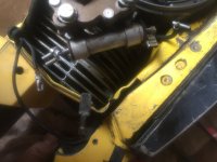
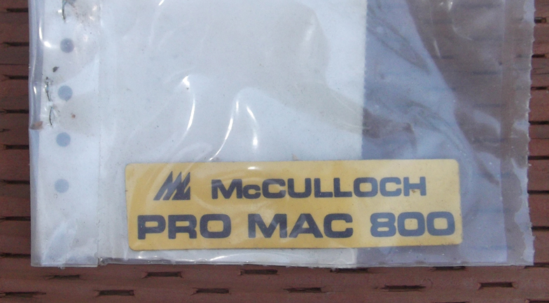
Found this on Craig’s List about 2 hours from me for $80. I don’t think I’d be able to justify this one with the wife though. It appears to have the original bar on it as well.
Attachments

fossil
Pinnacle OPE Member
- Local time
- 8:42 AM
- User ID
- 374
- Joined
- Jan 1, 2016
- Messages
- 1,743
- Reaction score
- 7,622
- Location
- Ontario, Canada
Timber Bear manual oiler.
Any Timber Bear enthusiasts out there?
The Timber Bear I received runs like a top but the manual and auto oilers do not appear to be working. The pump diaphragm feels pretty good and I have the material to make another if that doesn't cut it. The auto oiler adjustment screw is backed out all the way.
I have run some solvent through the oiler and it appear to be clean with no blockages and I did blow air through the pick up barb and the discharge passage with the oiler off of the saw
I found the oil line in three pieces and that's been fixed. The brass check valve in the oiler appears to be functioning.
Before I put it back together I thought I'd try the manual oiler to see if it worked by feeding the oiler through the pick up line from a can of bar oil. It is pushing the oil back through the line on the plunger in stroke but does draw oil up on the plunger return stroke .
No oil makes it to the discharge port in the saw case flange. I installed a new oiler base gasket.
I seems like check valve issue as it pumps oil when the oiler is immersed in bar oil.
I did find a little disc in the manual oiler plunger barrel that's about 1/8" in diameter. I'm wondering if that's a little check valve?
If it is, I would have no idea how it found it's way into the plunger barrel.
Any thoughts on what's gong on?
- Local time
- 7:42 AM
- User ID
- 639
- Joined
- Jan 21, 2016
- Messages
- 8,016
- Reaction score
- 42,570
- Location
- Missouri
Here is a couple better pictures. There are 4 wires that are disconnected. One from a condenser below the flywheel, two wires coming from the handle and another from under the flywheel. The larger condenser above the coil had a connection on each side. I’m just not sure what goes where. Crossing my fingers that the diagram Steve has will have what I need.
I have what you are looking for. Just be patient! Ill be home tomorrow.
") Dont accidently hook something up wrong. If you fry something you cant just run to walmart and get a new one.
Dont accidently hook something up wrong. If you fry something you cant just run to walmart and get a new one.- Local time
- 7:42 AM
- User ID
- 714
- Joined
- Jan 28, 2016
- Messages
- 2,817
- Reaction score
- 18,947
- Location
- Dike, Iowa

The large "condenser" is actually a ballast resistor.
Mark
RickZ
Active OPE Member
- Local time
- 6:42 AM
- User ID
- 10585
- Joined
- Sep 28, 2019
- Messages
- 13
- Reaction score
- 22
- Location
- New Mexico
I have a 2.3 McCulloch that I fought with the oiler for some time. It had a small fiber disc but it was part of the plunger not separate? Maybe it broke from somewhere? I could blow air through and everything but no oil. Inside the plastic housing was a small metal insert, where the oil should be coming from, it was partially clogged. After I cleaned it still nothing, because I hadn’t pushed it in far enough to line up the holes, after several head banging tries, it works like a champ.Timber Bear manual oiler.
Any Timber Bear enthusiasts out there?
The Timber Bear I received runs like a top but the manual and auto oilers do not appear to be working. The pump diaphragm feels pretty good and I have the material to make another if that doesn't cut it. The auto oiler adjustment screw is backed out all the way.
I have run some solvent through the oiler and it appear to be clean with no blockages and I did blow air through the pick up barb and the discharge passage with the oiler off of the saw
I found the oil line in three pieces and that's been fixed. The brass check valve in the oiler appears to be functioning.
Before I put it back together I thought I'd try the manual oiler to see if it worked by feeding the oiler through the pick up line from a can of bar oil. It is pushing the oil back through the line on the plunger in stroke but does draw oil up on the plunger return stroke .
No oil makes it to the discharge port in the saw case flange. I installed a new oiler base gasket.
I seems like check valve issue as it pumps oil when the oiler is immersed in bar oil.
I did find a little disc in the manual oiler plunger barrel that's about 1/8" in diameter. I'm wondering if that's a little check valve?
If it is, I would have no idea how it found it's way into the plunger barrel.
Any thoughts on what's gong on?
I know it’s not the same model but maybe give you somewhere to look if it’s similar.
Al Smith
Here For The Long Haul!
- Local time
- 8:42 AM
- User ID
- 537
- Joined
- Jan 14, 2016
- Messages
- 6,125
- Reaction score
- 13,527
- Location
- North western Ohio
I tried to make sense of what little info I have and thought perhaps that was the intent with the charging portion of the starter /generator circuit .My info doesn't indicate the resister rating or the voltage value of the battery pack .I did however find an IPL of the 5-10 E dated 1971 in the big black book .A partial theory of operation was on micro fiche with reference to something I don't think I have .Interesting subject .
- Local time
- 7:42 AM
- User ID
- 714
- Joined
- Jan 28, 2016
- Messages
- 2,817
- Reaction score
- 18,947
- Location
- Dike, Iowa
The individual cells in the battery pack were/are 1.2V and their are 10 in series so 12 volt for the system. Charging is limited around 14.5v maximum by the on board voltage regulator.
Mark
Mark
Last edited:
- Local time
- 5:42 AM
- User ID
- 232
- Joined
- Dec 24, 2015
- Messages
- 8,939
- Reaction score
- 62,265
- Location
- Coastal Oregon
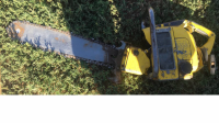
I was rooting through a box of parts today and came across this - if one of you guys want this, get me an address and I'll shoot it your way:
Last edited:
Al Smith
Here For The Long Haul!
- Local time
- 8:42 AM
- User ID
- 537
- Joined
- Jan 14, 2016
- Messages
- 6,125
- Reaction score
- 13,527
- Location
- North western Ohio
I might mention,Jim Rigdon who worked at the same place as myself was who used the cells to rebuild some model of the electric start McCulloch battery .He once had a GTG a lot of people attended near Venedocia Ohio .He was on one or two forums and is on FB in case anybody wants to ask him how he did it .
Dream
Mastermind Approved!
- Local time
- 8:42 AM
- User ID
- 7152
- Joined
- Aug 27, 2018
- Messages
- 8,274
- Reaction score
- 44,590
- Location
- Elberton, GA
Just search for the batteries on Amazon or ebay. Sub C lithium ion cells can be bought for cheap. The resistor can be bought for cheap, as long as you know the resistance (this can be determined with a cheap ohmeter if its not badly burned out)and power value(watts at given voltage, which seems to be 12 ). Brushes can even be bought cheap. Just mesure the dimensions and get the connection configuration. Same with buying seals and bearings. You just need to be able to measure the dimensions of the bearings or seals, and give a fairly accurate environmental range that they will be used in. IE temperature, duration, etc.
It's not magic. Its all common components that can be had cheaply now, thanks to the ole interest. Just take your time and sort it out.
All I'm saying is, think about this logically, as an engineer would do. They dont have things researched and developed as a first choice. They find out if an existing product is available to satisfy the need. Proprietary measures are sometimes taken, but careful analysis can usually determine if a standard product can be substituted.

Al Smith
Here For The Long Haul!
- Local time
- 8:42 AM
- User ID
- 537
- Joined
- Jan 14, 2016
- Messages
- 6,125
- Reaction score
- 13,527
- Location
- North western Ohio
Interesting wiring diagram but a little hard to follow .Evidently the circuitry at the right hand side of the page with what appears to be an npn transistor is the regulator .What the two zener diodes do I'm not certain .I assume the two diamond shapes shown in what would be the rotor area would be the brushes . What confuses me is the positive side of the battery pack ground or the negative ?When the start switch is applied it appears,unless I'm looking at it wrong that it completes the circuit from the positive side of the battery to ground bypassing the diode .
- Local time
- 7:42 AM
- User ID
- 639
- Joined
- Jan 21, 2016
- Messages
- 8,016
- Reaction score
- 42,570
- Location
- Missouri
Interesting wiring diagram but a little hard to follow .Evidently the circuitry at the right hand side of the page with what appears to be an npn transistor is the regulator .What the two zener diodes do I'm not certain .I assume the two diamond shapes shown in what would be the rotor area would be the brushes . What confuses me is the positive side of the battery pack ground or the negative ?When the start switch is applied it appears,unless I'm looking at it wrong that it completes the circuit from the positive side of the battery to ground bypassing the diode .
Yes, these are positive ground.
Al Smith
Here For The Long Haul!
- Local time
- 8:42 AM
- User ID
- 537
- Joined
- Jan 14, 2016
- Messages
- 6,125
- Reaction score
- 13,527
- Location
- North western Ohio
With that in mind the blocking diode in the start circuit most likely is to block any transients from the mag which might interfere with the start/generation circuitry .The mag or course being pulsating DC .
Similar threads
- Replies
- 16
- Views
- 1K